Schneider 140ACO13000 Analog Output Module Installation Guide (Wiring & Commissioning)
Time:2026-10-19 Browse: 1
Schneider 140ACO13000 Analog Output Module Installation Overview
The Schneider 140ACO13000 analog output module requires correct rack installation, output-channel configuration, and field wiring to deliver reliable analog control signals. During installation and commissioning, the main priorities are verifying hardware compatibility, confirming the configured output range, and checking whether the field device responds correctly to commands from the PLC controller.
A module that appears online in the control system may still produce an incorrect field signal if its channel settings, common wiring, or output scaling are inconsistent. This Installation Guide focuses on practical checks that help distinguish configuration problems from electrical faults before the system enters normal operation.
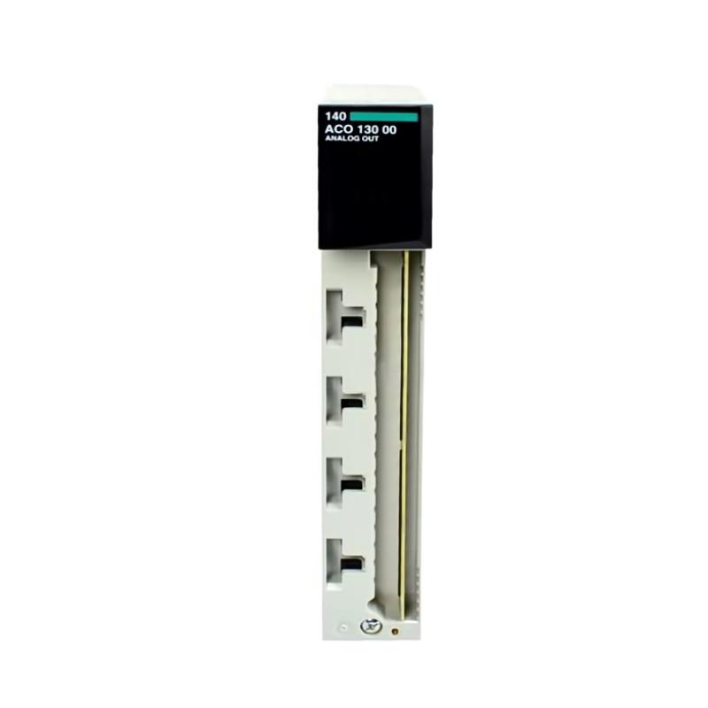
Hardware Preparation and System Configuration for the 140ACO13000
Before installing the Schneider 140ACO13000, confirm the module's exact catalog number, the compatible Quantum PLC rack, the power supply arrangement, and the hardware configuration defined in the engineering project. Verify the manufacturer's documentation for terminal assignments, channel characteristics, and supported output ranges rather than relying on a wiring diagram from a similar analog output module.
Prepare the following items:
The approved PLC hardware configuration and I/O assignment list.
The module wiring diagram and terminal identification.
A suitable digital multimeter for electrical verification.
The field-device specifications, including signal type and input impedance.
The approved commissioning procedure and electrical isolation equipment.
Record the intended PLC output address, engineering-unit range, and corresponding electrical signal for every channel. For example, a valve command of 50% must correspond to the expected electrical output under the configured scaling. The exact voltage or current value depends on the channel configuration and the field-device interface.
Rack Installation and Analog Output Wiring Considerations
Install the module in its designated rack position using the approved Schneider Electric installation procedure. Isolate the equipment as required before handling the module or field wiring, and observe the applicable electrostatic-discharge precautions.
During wiring, keep analog signal conductors separated from high-current switching cables and variable-frequency-drive motor wiring where the installation design permits. Use the specified cable type, shielding method, grounding arrangement, and terminal connections for the application.
Particular attention should be given to the signal return and common connections. A loose terminal or an incorrectly referenced common can cause an output reading that changes with nearby equipment activity. Do not assume that the signal common, protective earth, and cable shield are interchangeable.
Before energizing the circuit, compare each field connection against the verified terminal diagram. Confirm that the connected actuator or controller accepts the actual output signal generated by the configured channel.
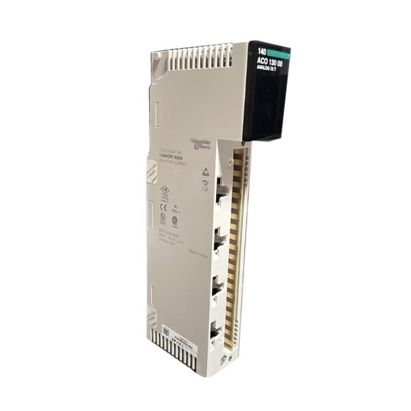
Schneider 140ACO13000 Setup and Commissioning Procedure
Commissioning should begin with a controlled test rather than immediately commanding the process to its normal operating range.
First, verify that the PLC recognizes the installed module and that the configured rack position and I/O address agree with the physical installation. Review the controller's module status and diagnostic information for configuration mismatches or channel faults.
Next, confirm the output-channel configuration and the PLC program's scaling logic. Check that raw output values, engineering units, and electrical output ranges are consistent. A value displayed as 50% is not sufficient evidence that the channel is producing the expected field signal.
Apply a safe test command using the approved commissioning procedure. Measure the output at the designated test point with a suitable instrument and compare the result with the manufacturer's specifications. Where practical, verify the signal at both the module output and the receiving device to identify voltage drop, wiring errors, or an incorrect reference.
For example, if the project is configured for a nominal 0–10 V signal, a 50% test command would normally correspond to approximately 5 V under linear scaling. This is an illustrative calculation, not confirmation that every 140ACO13000 channel supports that range. Use the verified channel specification before applying the test.
Field Validation of Schneider 140ACO13000 Output Performance
After the electrical test, verify that the field device responds in the correct direction and over the expected operating range. A rising PLC command should produce the intended change in the controlled device, subject to the configured signal characteristics and application logic.
In a representative commissioning scenario, a valve command may increase from 20% to 60% while the measured output changes by less than expected. The engineer should compare the commanded value, the configured scaling, the measured signal at the module, and the signal received by the actuator before replacing any hardware. This example illustrates a diagnostic method rather than a documented field event involving this exact module.
Record the test commands, measured values, channel assignments, diagnostic status, and final System Configuration. Confirm that normal interlocks and protective functions remain active throughout testing.
Schneider 140ACO13000 Installation Guide: Long-Tail Technical Checks
For engineers searching for Schneider 140ACO13000 analog output module wiring, setup, commissioning, or PLC output calibration guidance, the most useful checks are the ones that establish a traceable relationship between the controller command and the physical signal.
The commissioning record should answer three questions: Is the correct module installed? Is the channel configured for the intended signal? Does the field device receive the expected output?
If all three conditions are verified, the installation can proceed to process-level validation. If they are not, resolve the discrepancy before releasing the channel for operation.