Schneider 140ACO13000 Analog Output Module Troubleshooting (4–20 mA Signal Faults)
Time:2026-10-19 Browse: 1
Diagnosing Schneider 140ACO13000 Analog Output Current Problems
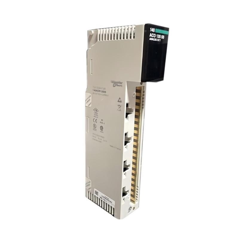
Schneider 140ACO13000 analog output module faults involving a missing or incorrect 4–20 mA signal should be investigated by checking the output command, channel diagnostics, external loop supply, and field wiring before concluding that the module has failed. This Modicon Quantum PLC Module provides eight analog current outputs and supports several configurable current ranges, including 4–20 mA and 0–20 mA.
A channel can receive a valid command from the PLC controller without delivering the expected current to the field instrument. The diagnostic objective is to determine whether the discrepancy originates in System Configuration, output scaling, an open current loop, an external supply problem, or the output hardware itself.
When Schneider 140ACO13000 Channel Fault Indicators Become Important
The first useful observation is the module's local LED status. The 140ACO13000 provides a green Active indicator for bus communication, a red external-fault indicator, eight green channel-on indicators, and eight red channel-fault indicators.
These indicators should be interpreted alongside the controller's I/O status and the measured field signal. A green bus indicator alone does not prove that every output channel is operating correctly.
For a 4–20 mA application, an open-loop condition deserves particular attention because the module identifies open circuit as a supported fault type for this range. A disconnected conductor, loose terminal, or interrupted field-device connection may explain the symptom more readily than an internal electronic failure.
Before disturbing the wiring, record the affected channel, its commanded output value, the relevant LED states, and any controller diagnostics. This creates a useful baseline for Fault Diagnosis.
A Practical Schneider 140ACO13000 Troubleshooting Case
Consider a representative field scenario in which a PLC command changes from 25% to 75%, but the connected valve positioner continues reporting a low input signal.
The initial observation does not establish whether the analog output module is defective. The investigation should compare four pieces of evidence:
PLC command: Confirm that the program value actually changes and is not being overwritten by another logic block.
Channel configuration: Verify the selected current range and the raw-count scaling used by the application.
Electrical measurement: Measure loop current with an appropriate instrument and approved procedure.
Field-device response: Check whether the measured current reaches the positioner and falls within its specified input range.
For a correctly scaled linear 4–20 mA signal, a 25% command corresponds to 8 mA, while a 75% command corresponds to 16 mA. These values are valid only when the channel and application are configured for that range.
If the PLC value changes correctly but the current remains nearly constant, the next diagnostic step is to compare the signal at the module output with the signal at the receiving device. If both are incorrect, investigate configuration, loop power, and module diagnostics. If the module-side signal is correct but the receiving-device signal is not, concentrate on the field wiring and loop connections.
This is an illustrative troubleshooting case, not a claim of a documented repair performed on a specific installation.
Schneider 140ACO13000 Fault Diagnosis Through Signal Measurement
A disciplined measurement sequence prevents unnecessary component replacement.
First, verify that the external loop supply is within the module's specified 6–30 V DC range and that the complete circuit meets the applicable voltage-drop requirements. The supply voltage must be evaluated under the actual load, not only at an unloaded power supply.
Second, check the current loop using a suitable meter and the correct measurement method. Never connect an ammeter directly across a voltage source. Follow the approved isolation procedure and account for the possibility that interrupting the loop may affect the controlled process.
Third, compare the measured current with the configured PLC output value. The module supports multiple ranges and count formats, including 4–20 mA represented by 0–4095 counts or 0–16000 counts. The selected format must match the program's scaling calculation.
For example, if a project uses the 0–4095 representation for a 4–20 mA output, the approximate expected current can be calculated as:
Expected current = 4 mA + (raw count / 4095 × 16 mA)
A raw count of approximately 2048 therefore represents roughly 12 mA, assuming the documented scaling is configured and applied as intended. A different count format requires a different conversion.
Correcting Schneider 140ACO13000 Open-Loop and Wiring Faults
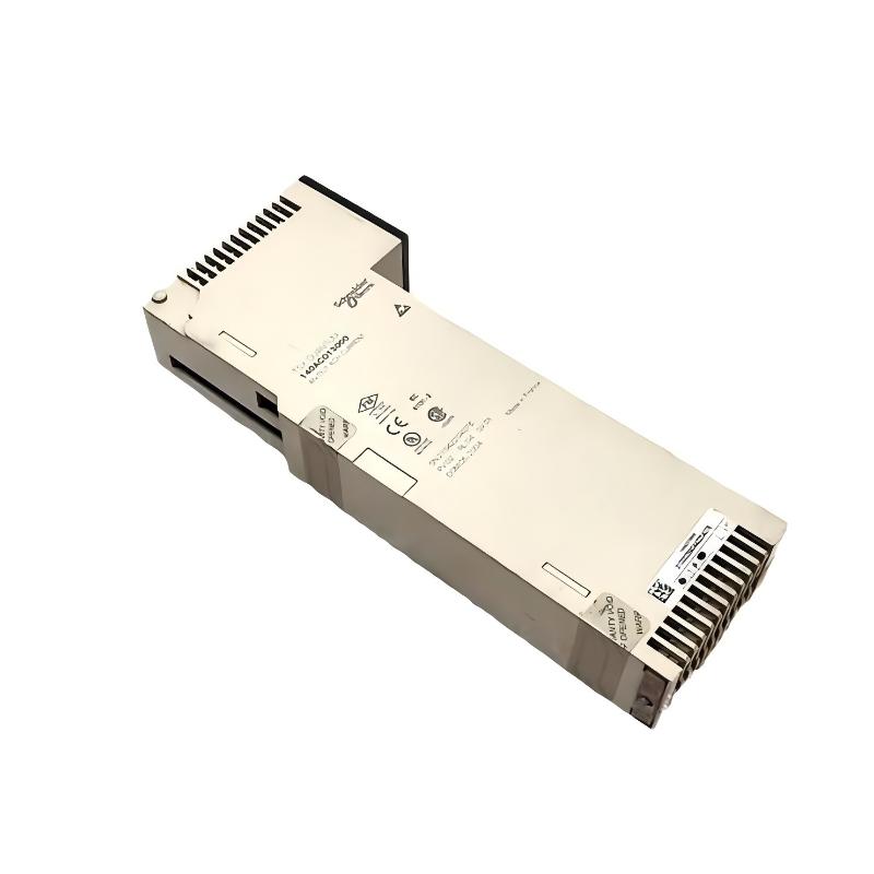
If the diagnostics point to an open current loop, inspect the wiring diagram and terminal assignments before changing any connections. Check for loose conductors, damaged cables, disconnected field-device terminals, and incorrect signal-return wiring.
The module documentation identifies terminals labeled RETURN as internally common. This detail matters when checking the wiring arrangement, but it does not eliminate the need to follow the specified connection diagram and field-device requirements.
After correcting a confirmed wiring problem, restore the circuit according to the site's electrical safety procedure. Verify the channel-fault indication, repeat the current measurement, and confirm that the field instrument responds to changes in the PLC command.
If the loop is intact but the output remains incorrect, review the configured range, raw-count conversion, external supply, and channel status before considering module replacement. If the fault persists after these checks, use the manufacturer's diagnostic procedure to determine whether further testing or repair is warranted.
Schneider 140ACO13000 Output Faults That Can Resemble Hardware Failure
Not every incorrect analog signal indicates a failed output stage. Several conditions can produce similar symptoms:
Incorrect output scaling: The PLC program may generate a valid numerical value using a different count range than the configured channel.
External loop supply problems: Insufficient voltage under load can prevent the current loop from operating as expected.
Field wiring interruption: An open conductor or poor connection can interrupt current delivery even when the PLC remains online.
Channel configuration mismatch: The engineering project's selected range may not agree with the requirements of the connected instrument.
Possible module hardware failure: If configuration, wiring, supply conditions, and field-device compatibility have been verified, a hardware fault becomes a more reasonable hypothesis.
The most useful field practice is to eliminate these causes in a logical order. Replacing a module before confirming the electrical signal and channel settings can introduce additional downtime without addressing the original fault.
Schneider 140ACO13000 Troubleshooting and Repair Validation
A repair should not be considered complete merely because the fault LED turns off. The final verification must demonstrate that the analog output behaves correctly across the required operating range.
Apply several approved test commands, such as 0%, 25%, 50%, 75%, and 100%, where the process can safely accommodate them. For a 4–20 mA configuration, the corresponding ideal currents are 4, 8, 12, 16, and 20 mA. Confirm that the actual channel configuration supports these endpoints and that the connected equipment accepts the test conditions.
Record the commanded values, measured currents, channel diagnostics, and field-device response. Where applicable, repeat the test after the system returns to its normal operating configuration.
For long-tail searches such as Schneider 140ACO13000 4–20 mA output troubleshooting, Modicon Quantum analog output channel fault diagnosis, and 140ACO13000 open-loop fault repair, this measurement-based approach provides a practical way to separate configuration errors from wiring faults and potential hardware failures.