Schneider 140CHS11000 Hot Standby Module Installation Guide for Quantum PLC Systems
Time:2026-10-21 Browse: 0
Overview: Schneider 140CHS11000 Hot Standby Installation
The Schneider Electric 140CHS11000 Hot Standby Module is designed for Modicon Quantum PLC systems that require redundant control and automatic switchover capability. A reliable 140CHS11000 installation depends on matching the primary and standby controllers, verifying system configuration, and establishing a stable fiber-optic communication link before commissioning. Incorrect A/B designation, mismatched hardware, or a faulty communication cable can prevent the redundant system from entering its expected operating state.
How the 140CHS11000 Supports PLC Redundancy
In a Quantum Hot Standby architecture, two compatible PLC systems operate as primary and standby controllers. The primary executes the application control logic, while the standby maintains the required synchronization so it can assume control when the primary system fails.
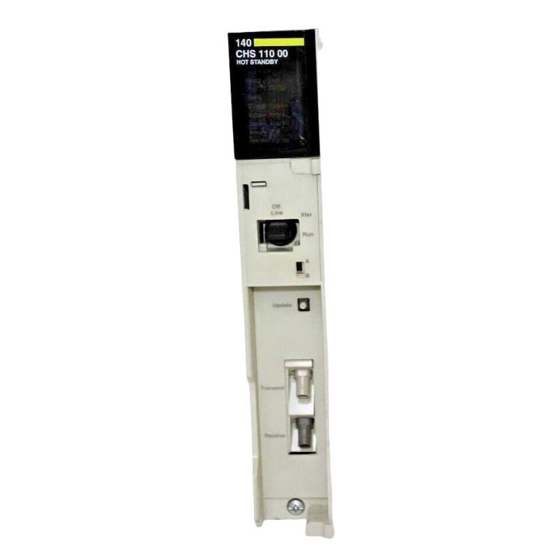
The 140CHS11000 Hot Standby Module provides the communication interface between the redundant systems. Its front-panel indicators help engineers assess module readiness, communication activity, communication errors, and operating role.
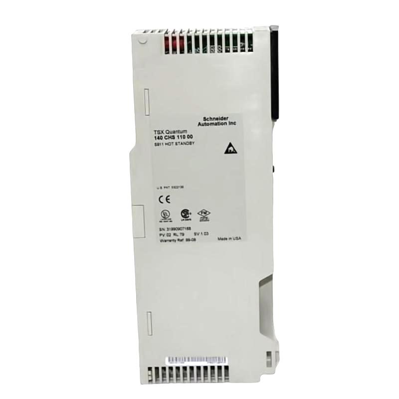
Before beginning this Installation Guide, confirm that both racks contain compatible Quantum power supplies, CPUs, remote I/O head processors, and hot standby modules. The corresponding hardware and software revisions must satisfy the requirements of the installed system.
Installation Preparation and System Configuration
Prepare the following items before mounting the modules:
Two compatible Modicon Quantum backplanes with sufficient available slots.
Matching hot standby modules and compatible controller hardware.
Compatible power supplies installed in both racks.
The specified fiber-optic communication cable and connectors.
The applicable Quantum Hot Standby documentation and configuration software.
Inspect the module labels and record the hardware and firmware revisions. Compare the configuration tables, I/O maps, and segment scheduler settings of the two controllers. These checks are particularly important when adding redundancy to an existing PLC installation.
The 140CHS11000 is a legacy product. Confirm that the installed hardware revisions, replacement modules, and engineering software are compatible with the existing Quantum system before commissioning.
Mounting and Fiber-Optic Wiring for the 140CHS11000
Install the modules in the designated slots of the primary and standby racks according to the system documentation. Keep the rack layouts consistent, particularly for corresponding controllers and remote I/O head processors.
Set the designation slide switches to opposite positions: one module must be designated A and the other B. An incorrect designation can prevent the intended hot standby configuration from operating properly.
Connect the transmit and receive fiber-optic ports according to the documented cable arrangement. Do not assume that two apparently connected fiber strands are correctly crossed. Verify the transmit-to-receive path at both ends, inspect connectors for contamination, and check the cable for sharp bends or physical damage.
For installations extending beyond the supplied short cable, confirm the specified fiber type, connector style, optical link budget, and maximum supported distance against the applicable hardware manual. The cable arrangement must be suitable for the actual installation rather than selected solely by physical fit.
Schneider Quantum PLC Setup and Commissioning
Commission the redundant system in a controlled sequence:
Verify that both racks are fully assembled and that the primary and standby configurations match.
Confirm that the A/B designation switches are opposite and the fiber-optic connection is correct.
Verify the controller program, configuration tables, I/O maps, and segment scheduler settings.
Set the hot standby module keyswitches to the documented Run position.
Start the first controller system and confirm its expected primary operating status.
Start the second system and check whether it reaches the expected standby state.
Review the front-panel LEDs and controller diagnostics before authorizing normal process operation.
Do not judge commissioning success from the Ready LED alone. A module can pass its initial diagnostics while the redundant communication link or synchronization process remains faulty.
Field Validation of the 140CHS11000 Hot Standby System
During commissioning, record the initial LED states, controller status, active role, and communication diagnostics for both racks. Confirm that the standby controller is synchronized and that the application is prepared for a controlled switchover test.
In a representative commissioning scenario, a system may show a green Ready indicator on both modules while the standby controller fails to establish the expected operating role. Rather than replacing hardware immediately, an engineer should first compare the A/B switch positions, verify the fiber transmit/receive path, and compare the two PLC configurations. These checks isolate common setup errors before component replacement is considered.
This is an illustrative diagnostic scenario, not a verified field-service record. Actual acceptance criteria and switchover timing must be taken from the installed system's documentation and test results.
Long-Tail Keywords for Schneider 140CHS11000 Installation
This guide addresses Schneider 140CHS11000 Hot Standby Module installation, Modicon Quantum PLC redundancy setup, Quantum hot standby fiber-optic wiring, 140CHS11000 commissioning procedures, primary and standby controller synchronization, and PLC system configuration validation.
A successful Setup / Commissioning process should demonstrate consistent controller configuration, correct module designation, reliable communication, and verified standby readiness before the redundant PLC system is returned to service.