Schneider 140CHS11000 Hot Standby Module Troubleshooting: Standby Communication Fault Diagnosis
Time:2026-10-21 Browse: 0
Recognizing Schneider 140CHS11000 Communication Faults
Schneider 140CHS11000 Hot Standby Module communication faults can prevent a Modicon Quantum PLC system from establishing or maintaining its redundant standby state. Before declaring the module defective, engineers should investigate the fiber-optic link, A/B designation, controller compatibility, and diagnostic LED patterns. A green Ready indicator does not, by itself, confirm that communication between the primary and standby systems is functioning correctly.
A Field-Oriented Fault Diagnosis Approach for the 140CHS11000
Consider a representative maintenance scenario: a Quantum PLC remains in primary operation, but the second rack does not enter the expected standby state after startup. The process controller is still running, so immediately replacing the primary module would introduce unnecessary operational risk.
The initial investigation should establish three facts:
Is the primary controller continuing to execute its application normally?
Does the standby rack report a communication error or an unexpected module status?
Did the fault appear after maintenance, cable replacement, a configuration change, or a power interruption?
These observations help distinguish a communication-path problem from a configuration mismatch or an internal module fault. The scenario is illustrative rather than a verified customer case.
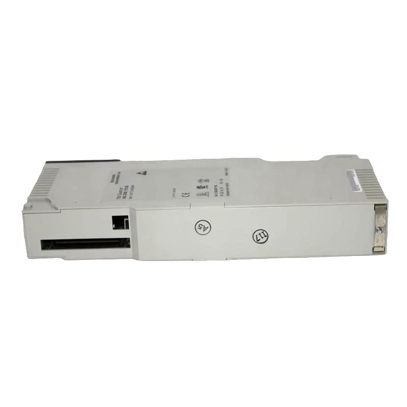
Interpreting 140CHS11000 LED Patterns During Troubleshooting
The 140CHS11000 provides several front-panel indicators, including Ready, Com Err, Com Act, Primary, and Standby. Their combined behavior is more useful than interpreting an individual LED in isolation.
| Observation | Diagnostic direction |
|---|---|
| Ready is not steadily illuminated | Investigate power, initialization, and module diagnostics. |
| Com Err is illuminated | Inspect the fiber-optic communication path and associated hardware. |
| Com Act blinks in a repeating pattern | Record the blink count and consult the applicable error-code table. |
| Ready is on, but standby status is absent | Check synchronization, designation switches, compatibility, and configuration. |
| The standby rack goes offline after a hardware change | Review the maintenance sequence, module status, and required restart procedure. |
LED meanings depend on the documented operating state and error pattern. Record the sequence before resetting the system; an unnecessary restart can erase useful evidence of an intermittent fault.
Diagnosing Fiber-Optic Link Failures on the Schneider 140CHS11000
Fiber-optic communication is a primary diagnostic target when the redundant systems cannot communicate.
Start with a physical inspection. Confirm that the transmit and receive connections follow the documented arrangement at both racks. Check connector seating, cleanliness, cable routing, and visible damage. Where appropriate, use a compatible optical source and power meter to assess the cable path against the specified optical requirements.
If the cable passes inspection, compare the module status at both ends. A fault isolated to one rack may indicate a local module, connector, or interface problem rather than a complete link failure.
Avoid replacing both modules simultaneously. Where the system documentation and site procedures permit, change one suspect component at a time and record the resulting diagnostic status. This preserves the ability to identify the actual cause.
Resolving 140CHS11000 Configuration and Synchronization Faults
A redundant PLC system can fail to establish standby operation even when its fiber-optic connection is intact.
Compare the primary and standby controllers for:
Compatible CPU and hot standby module hardware and software revisions.
Matching configuration tables and I/O maps.
Consistent segment scheduler settings.
Correct and opposite A/B designation switch positions.
Compatible power supply and remote I/O head processor arrangements.
Pay particular attention to recent program changes. A controller that was previously synchronized may fail to rejoin the redundant system after a configuration download or replacement of a key module.
Do not assume that matching application logic alone proves configuration compatibility. The relevant system configuration and firmware requirements must also be checked.
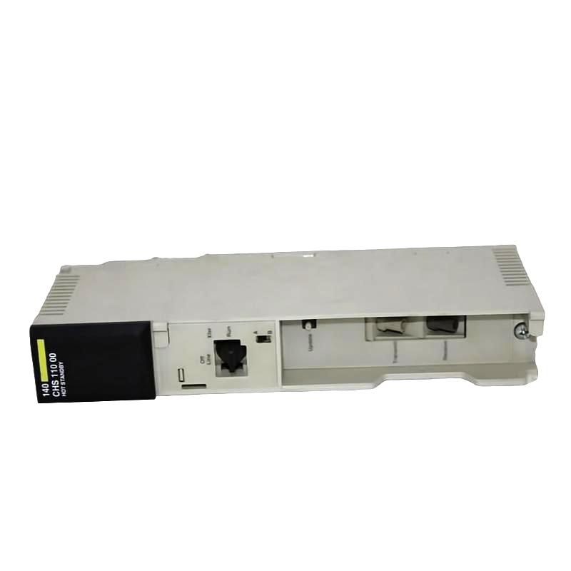
When 140CHS11000 Com Act Blink Codes Indicate an Internal Fault
Repeated Com Act blinking may indicate an internal interface or board-level diagnostic error. The documented CHS 110 error tables include faults associated with RAM tests, PROM checksums, UART initialization, and communication timeouts.
For example, a recorded seven-blink pattern should be checked against the applicable manual's error table rather than treated as a generic communication failure. The documented CHS 110 table associates seven blinks with PROM checksum error code 6301. Confirm the exact module revision and applicable documentation before acting on this interpretation.
If an internal diagnostic fault persists after the external communication path and system configuration have been verified, follow the manufacturer's troubleshooting and replacement procedure. Do not attempt board-level repair without the appropriate technical documentation, equipment, and authorization.
Recovery and Validation After a Schneider 140CHS11000 Fault
After correcting the suspected cause, verify that the module initializes correctly, communication is restored, and the standby controller reaches its expected synchronized state.
If a key module has been replaced or hot-swapped, follow the documented restart and program-update requirements for the affected system. Do not assume that physical replacement alone restores redundancy.
A controlled switchover test should only be performed under an approved maintenance procedure, with process safety and the consequences of losing the active controller considered in advance. Record the initial fault, corrective action, resulting LED states, and final controller roles.
For a representative fiber-link fault, the expected validation evidence would include the disappearance of the communication error, restored communication activity, and confirmed standby readiness. Numerical recovery times should be recorded from actual tests rather than estimated or presented as measured results.
Long-Tail Keywords for Schneider 140CHS11000 Fault Diagnosis
Relevant search topics include Schneider 140CHS11000 troubleshooting, Modicon Quantum Hot Standby communication fault diagnosis, 140CHS11000 Com Err LED, Quantum PLC standby synchronization failure, CHS 110 fiber-optic link troubleshooting, and 140CHS11000 module replacement procedures.
The most reliable troubleshooting strategy is to separate physical communication faults, configuration inconsistencies, and internal diagnostic errors before replacing hardware. This approach reduces unnecessary component changes and provides a clearer basis for restoring PLC redundancy.