Allen Bradley 20AD065A0AYNANC0 PowerFlex 70 AC Drive Installation Guide (Wiring & Commissioning)
Time:2026-10-30 Browse: 2
Understanding the Allen Bradley 20AD065A0AYNANC0 Drive Installation
Installing the Allen Bradley 20AD065A0AYNANC0 PowerFlex 70 AC Drive requires careful attention to incoming power connections, motor compatibility, grounding, and control parameter configuration. Incorrect installation can lead to DC bus faults, motor overcurrent trips, or unstable speed regulation during operation.
The 20AD065A0AYNANC0 is a three-phase, 480V AC PowerFlex 70 drive rated at 65 A, with a nominal power rating of 50 HP (37 kW). It includes a brake IGBT but does not have an internal braking resistor. These characteristics should be considered when planning the electrical installation and braking arrangement.
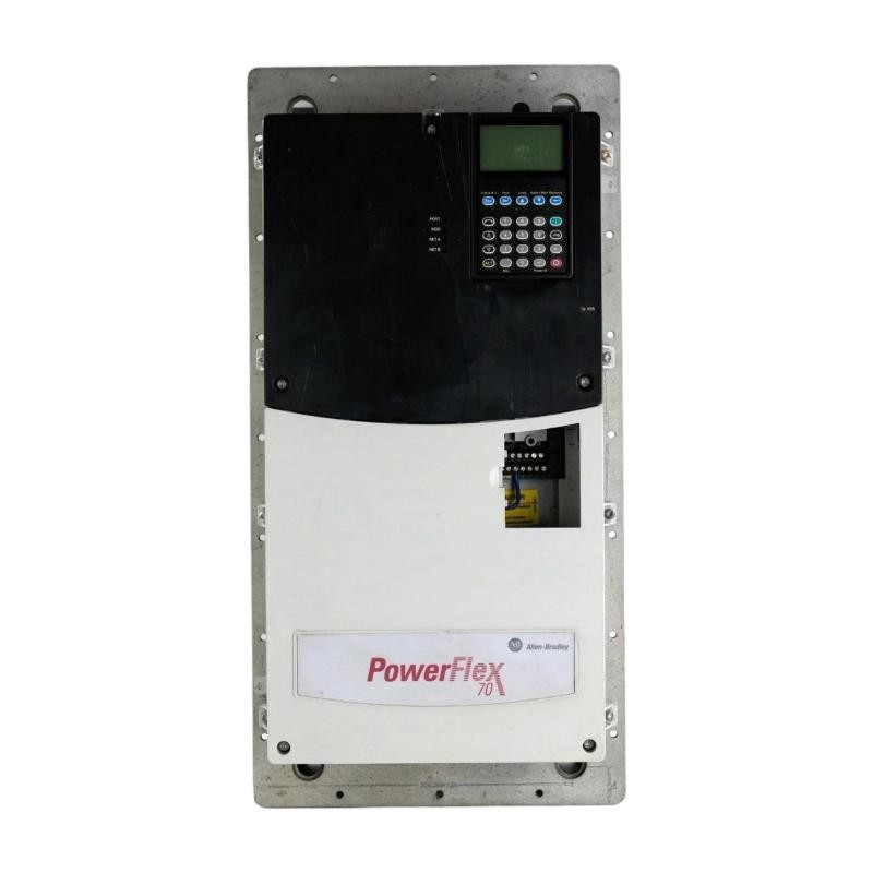
PowerFlex 70 Installation Requirements and Site Preparation
Before mounting the PLC-controlled drive system, verify that the electrical cabinet can accommodate the drive's frame size, ventilation requirements, and cable routing.
Important installation considerations include:
Confirm that the supply voltage matches the 480V AC drive rating.
Check that the upstream protective devices are correctly selected.
Ensure adequate cabinet ventilation and clearance around the heatsink.
Keep motor power cables separated from low-level analog signal wiring.
Use an appropriate protective earth connection.
Verify that the motor nameplate current does not exceed the drive's applicable operating rating.
The drive has an IP20 enclosure rating and is intended for installation within a suitable industrial enclosure.
A practical consideration is the cabinet's thermal environment. Even when the drive operates below its rated current, restricted airflow can gradually increase heatsink temperature and reduce operating reliability.
Allen Bradley 20AD065A0AYNANC0 Power and Motor Wiring
The incoming three-phase supply connects to the designated R/L1, S/L2, and T/L3 terminals. The motor connects to U/T1, V/T2, and W/T3.
The protective earth conductor must be connected to the designated grounding point according to the manufacturer's installation instructions.
For control wiring, identify the actual control terminal assignments before connecting start commands, speed references, and feedback signals. The control architecture should be documented as part of the overall System Configuration.
Recommended wiring practices include:
Use shielded motor cable where required by the installation environment.
Terminate cable shields according to the manufacturer's grounding recommendations.
Avoid routing analog reference cables alongside high-current motor conductors.
Verify terminal tightness using the specified torque values.
Check motor insulation and cable continuity before energizing the drive.
Never perform resistance or insulation testing through connected electronic drive circuitry. Isolate the drive and follow the manufacturer's testing procedure.
PowerFlex 70 Setup and Parameter Configuration
The Setup / Commissioning process should begin with confirming the motor nameplate information.
Typical configuration items include:
| Configuration Item | Required Information |
|---|---|
| Motor rated voltage | Motor nameplate |
| Motor rated current | Motor nameplate |
| Motor rated frequency | Motor nameplate |
| Motor rated speed | Motor nameplate |
| Minimum frequency | Application requirement |
| Maximum frequency | Motor and machine limits |
| Acceleration time | Mechanical load requirements |
| Deceleration time | Mechanical load and braking capability |
| Start source | Keypad or external control |
| Speed reference | Analog input or configured control source |
The 20AD065A0AYNANC0 version is supplied with a blank cover rather than an installed operator interface. An appropriate compatible programming interface or communication arrangement is therefore necessary for parameter access.
Do not assume that another PowerFlex 70 drive's parameter values can be copied without checking its motor, control firmware, and application configuration.
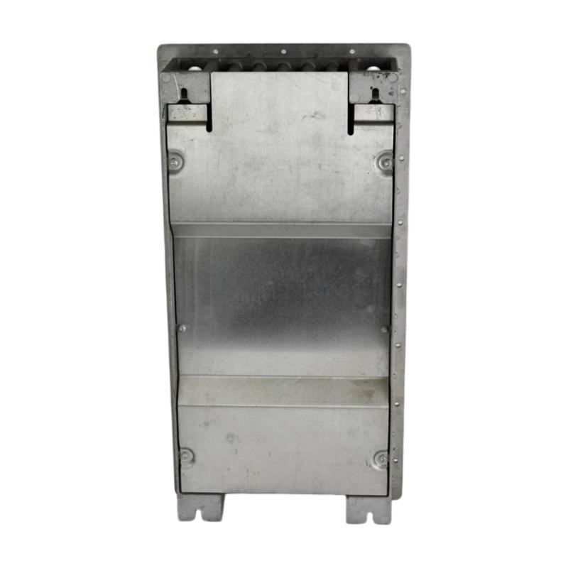
Commissioning Checks for the PowerFlex 70 AC Drive
Once electrical connections and parameters have been verified, commissioning can proceed under controlled conditions.
During the initial test, check:
Whether the drive completes its power-up sequence without reporting a fault.
Whether the displayed or communicated DC bus voltage is consistent with the incoming supply.
Whether the motor rotates in the intended direction.
Whether the output current remains within the motor's rated operating limits.
Whether acceleration and deceleration are smooth.
Whether external stop commands and protective interlocks work correctly.
For example, when testing a 50 HP motor, a technician should compare the actual motor current against its nameplate rating rather than assuming that the drive's 65 A capacity is the correct motor current setting.
A no-load test should be followed by a controlled load test. Sudden current increases during acceleration may indicate mechanical resistance, incorrect motor parameters, or an unsuitable acceleration profile.
Field Validation of Allen Bradley 20AD065A0AYNANC0 Installation
In one commissioning scenario involving a high-inertia conveyor, the drive completed its initial startup but experienced excessive current during acceleration.
Instead of immediately replacing the drive, the commissioning engineer checked the motor nameplate values, mechanical load condition, and acceleration settings.
The investigation showed that the acceleration profile was too aggressive for the connected load. After adjusting the ramp according to the mechanical requirements, the motor accelerated more consistently.
This example illustrates an important installation principle: drive commissioning should evaluate the complete motor-load system, not just whether the drive powers up successfully.
Long-Tail Keywords for PowerFlex 70 Installation
The following search phrases are relevant to this model and its application:
Allen Bradley 20AD065A0AYNANC0 installation guide
PowerFlex 70 480V AC drive wiring instructions
20AD065A0AYNANC0 setup and commissioning
Allen Bradley 65A AC drive parameter configuration
PowerFlex 70 motor connection and grounding
PowerFlex 70 50 HP drive startup procedure
PowerFlex 70 industrial drive System Configuration
Final Installation Considerations
A reliable PowerFlex 70 installation depends on correct electrical sizing, suitable environmental conditions, accurate motor data, and controlled commissioning. Recording the final parameter configuration and test results also makes future maintenance and Fault Diagnosis considerably easier.