Allen Bradley 20AD065A0AYNANC0 PowerFlex 70 DC Bus Overvoltage Troubleshooting Guide
Time:2026-10-30 Browse: 3
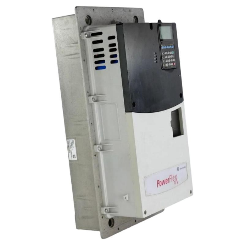
Identifying DC Bus Overvoltage Faults in the Allen Bradley 20AD065A0AYNANC0
An Allen Bradley 20AD065A0AYNANC0 PowerFlex 70 drive that trips during motor deceleration may be experiencing a DC bus overvoltage condition. This problem is particularly relevant to high-inertia machinery, where the motor can temporarily operate as a generator and return energy to the drive's DC bus.
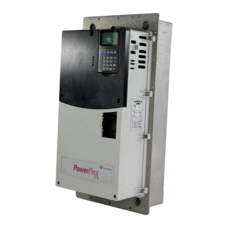
The 20AD065A0AYNANC0 is a 480V AC, 65 A PowerFlex 70 drive equipped with a brake IGBT but supplied without an internal braking resistor. Consequently, the braking arrangement and deceleration settings deserve particular attention when investigating overvoltage trips.
Replacing the drive immediately is rarely the best first response. A systematic Troubleshooting process should distinguish between excessive regenerative energy, incorrect deceleration configuration, supply disturbances, and an actual drive hardware problem.
PowerFlex 70 Overvoltage Fault Symptoms During Operation
A DC bus overvoltage problem may present itself in several ways:
The drive operates normally during acceleration but trips when stopping.
Faults occur more frequently when the machine carries a heavy load.
A conveyor or centrifuge stops successfully at low speed but trips during rapid deceleration.
The drive reports an overvoltage fault after an emergency stop or rapid speed reduction.
The DC bus voltage increases immediately before the drive shuts down.
The timing of the fault is important.
If the problem consistently occurs during deceleration, regenerative energy should be investigated before suspecting a defective power supply.
If the fault appears while the motor is operating at constant speed, incoming voltage fluctuations or other electrical problems may be more likely.
Engineering Fault Diagnosis: Why the DC Bus Voltage Increases
The PowerFlex 70 uses an internal DC bus to supply its inverter section.
During normal motoring operation, electrical energy flows from the incoming AC supply through the rectifier and DC bus to the motor.
During regenerative operation, the direction of energy flow changes. The motor returns mechanical energy to the electrical system, increasing DC bus voltage if the energy cannot be dissipated or otherwise managed.
For the 20AD065A0AYNANC0, the installed brake IGBT provides a switching element for an external dynamic braking arrangement. However, the drive does not include an internal braking resistor.
This distinction matters because having a brake IGBT does not mean the drive can independently dissipate unlimited regenerative energy.
Potential causes include:
Excessively short deceleration time.
Missing or incorrectly sized external braking resistor.
Incorrect braking configuration.
High-inertia mechanical loads.
Supply voltage instability.
DC bus monitoring or power-section abnormalities.
A Practical PowerFlex 70 Overvoltage Investigation
Consider a conveyor installation where the 20AD065A0AYNANC0 runs normally at operating speed but repeatedly trips when the conveyor stops.
The maintenance team initially suspects a damaged inverter section. However, the fault history shows that the problem only appears during deceleration.
The investigation should follow the actual operating sequence.
First, examine the fault timing.
Record the motor speed, load condition, and deceleration command immediately before the trip. Compare normal stops with fault-producing stops.
Next, inspect the braking arrangement.
Check whether an external braking resistor is installed and whether its resistance, power rating, duty cycle, and wiring comply with the PowerFlex 70 braking requirements.
Then, review the deceleration configuration.
Determine whether the configured ramp is realistic for the mechanical inertia. A rapid reduction in commanded frequency does not guarantee that the connected machinery can release its stored energy at the same rate.
Finally, evaluate the incoming supply and DC bus behavior.
Use suitable diagnostic equipment and the manufacturer's procedures to determine whether the DC bus rises during deceleration or whether the abnormal voltage originates from the supply.
Never probe energized DC bus terminals without appropriate qualifications, equipment, and electrical safety procedures. The DC bus can remain hazardous after incoming power is disconnected.
Corrective Actions for Allen Bradley 20AD065A0AYNANC0 Overvoltage Trips
The corrective action depends on the confirmed cause.
| Identified Problem | Recommended Corrective Action |
|---|---|
| Deceleration time too short | Increase the deceleration time within application limits |
| Braking resistor missing | Evaluate and install a correctly rated external braking resistor |
| Resistor overheating | Verify resistor duty cycle, resistance, and thermal protection |
| High mechanical inertia | Review the stopping profile and braking strategy |
| Supply voltage fluctuation | Inspect incoming supply and upstream electrical equipment |
| Suspected drive power-section damage | Perform manufacturer-approved hardware diagnostics |
For this particular drive, do not select a braking resistor based solely on the 65 A output rating. Resistor selection must account for regenerative energy, braking frequency, resistance limits, and the drive's applicable brake IGBT specifications.
PowerFlex 70 Repair Considerations and Recovery Validation
If configuration and braking corrections do not resolve the fault, further inspection of the drive may be necessary.
Qualified technicians should examine the braking circuit, DC bus components, power connections, and relevant control circuitry according to the manufacturer's repair procedures.
A drive that repeatedly trips with no connected motor or under conditions where regenerative energy is absent may require a different diagnostic path.
After corrective work, verify:
Stable DC bus voltage during operation.
Correct motor acceleration and deceleration.
Proper external braking resistor operation.
No recurrence of the original fault.
Normal performance under representative load conditions.
A successful repair should be demonstrated through repeated controlled operating cycles, not simply by clearing the fault code.
Real-World Troubleshooting Lessons for PowerFlex 70 Drives
In field maintenance, one common diagnostic mistake is treating every DC bus overvoltage fault as evidence of failed drive hardware.
For example, a conveyor drive may operate normally for several hours before tripping during a heavily loaded stop. Replacing the inverter assembly without checking the braking circuit may leave the original problem completely unresolved.
The more reliable engineering approach is to correlate the fault with motor speed, load inertia, deceleration time, and braking resistor performance.
For the 20AD065A0AYNANC0, the absence of an internal braking resistor makes this verification especially important.
Long-Tail Keywords for PowerFlex 70 Fault Diagnosis
Relevant search terms for this troubleshooting scenario include:
Allen Bradley 20AD065A0AYNANC0 troubleshooting
PowerFlex 70 DC bus overvoltage fault
20AD065A0AYNANC0 braking resistor problems
Allen Bradley PowerFlex 70 deceleration fault diagnosis
PowerFlex 70 external dynamic braking repair
PowerFlex 70 480V drive overvoltage protection
65A PowerFlex 70 regenerative braking troubleshooting
Restoring Reliable Operation of the PowerFlex 70 Drive
Resolving DC bus overvoltage faults requires understanding how the motor, mechanical load, braking circuit, and drive interact during deceleration. On the Allen Bradley 20AD065A0AYNANC0, checking the external braking arrangement and reviewing the stopping profile should be part of the initial Troubleshooting process.
Accurate fault records, appropriate electrical measurements, and controlled recovery testing provide a more dependable basis for repair than replacing components without confirming the root cause.