Allen Bradley 20F11NC2P1JA0NNNNN PowerFlex 753 AC Drive Installation Guide (Wiring & Setup)
Time:2026-10-30 Browse: 3
PowerFlex 753 20F11NC2P1JA0NNNNN Installation Overview
The Allen Bradley 20F11NC2P1JA0NNNNN PowerFlex 753 AC Drive requires correct three-phase power wiring, motor parameter configuration, and control signal verification to achieve stable operation. This model is designed for 400V-class industrial applications and provides a nominal output current of 2.1 A, making accurate motor matching particularly important during installation.
This PowerFlex 753 drive features embedded I/O, forced-air cooling, an integrated EMC filter, and a dynamic braking transistor. It uses a Frame 2 configuration and an IP20/IP00 open-type enclosure. The supplied configuration does not include a Human Interface Module (HIM), so an appropriate programming interface must be arranged before commissioning.
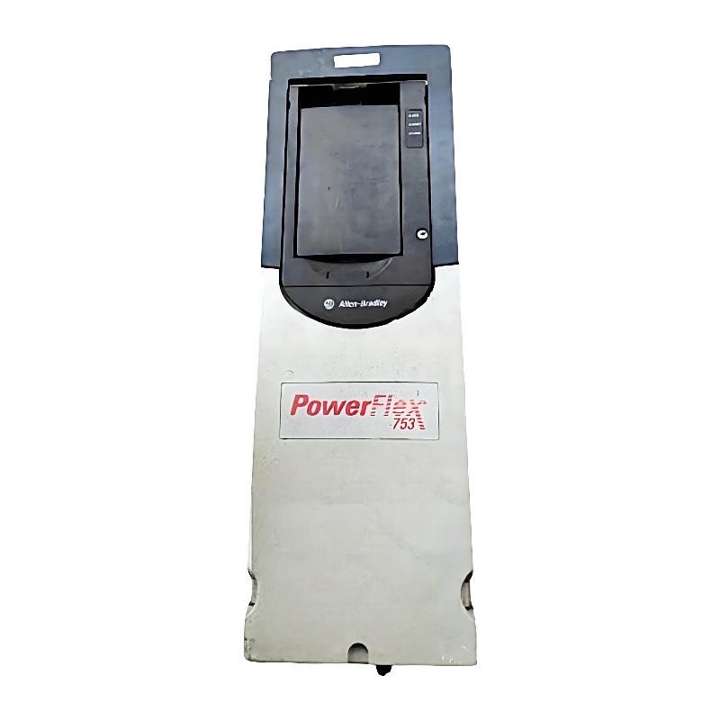
Technical Characteristics Affecting Drive Installation
Before preparing the electrical cabinet, confirm the following model-specific characteristics:
| Parameter | Specification |
|---|---|
| Product Type | AC Variable Frequency Drive |
| Drive Family | PowerFlex 753 |
| Catalog Number | 20F11NC2P1JA0NNNNN |
| Nominal Input Voltage | 400V AC |
| Input Phases | 3-phase |
| Nominal Output Current | 2.1 A |
| Normal Duty Power | 0.75 kW |
| Heavy Duty Power | 0.75 kW |
| Frame Size | Frame 2 |
| Enclosure | IP20/IP00 |
| Cooling | Forced Air |
| EMC Filter | Integrated |
| Dynamic Braking | Braking Transistor |
| Operator Interface | No HIM supplied |
The exact supply voltage range and motor operating limits must be checked against the drive nameplate and Rockwell Automation technical documentation.
Preparing the PowerFlex 753 Electrical Cabinet
The 20F11NC2P1JA0NNNNN is intended for vertical panel mounting inside an appropriately designed industrial enclosure. Its open-type enclosure does not provide protection against unrestricted exposure to dust, moisture, or conductive contaminants.
Cabinet preparation should address three practical issues.
Thermal management: The forced-air cooling system requires unobstructed airflow. Avoid positioning heat-generating components directly below the drive where rising hot air can increase its intake temperature.
Electrical separation: Keep motor output cables away from low-level analog signals, encoder wiring, and communication cables. This reduces the possibility of electrical interference affecting speed references and feedback signals.
Maintenance accessibility: Leave sufficient space for terminal inspection, cooling-path cleaning, and future replacement of option modules.
The integrated EMC filter and installed common-mode jumper should also be considered when evaluating the plant grounding arrangement and any special residual-current protection requirements.
Three-Phase Power and Motor Connection
For the main power circuit, connect the incoming three-phase supply to the designated R/L1, S/L2, and T/L3 input terminals.
The motor output connections are:
U/T1
V/T2
W/T3
Connect the protective earth conductor to the designated PE grounding terminal.
The input supply and motor cable must be selected according to the applicable electrical code, drive current rating, installation method, ambient temperature, and upstream protective-device requirements.
For a motor operating near the drive's 2.1 A nominal output rating, verify that the motor nameplate current and duty classification are compatible with the selected drive configuration.
Do not assume that a 0.75 kW motor is automatically suitable simply because its power rating matches the drive. Voltage, current, frequency, service conditions, and load characteristics must also be considered.
PowerFlex 753 Control Wiring and System Configuration
The PowerFlex 753 includes embedded I/O and supports additional functionality through its slot-based option architecture.
A typical System Configuration may include:
PLC-generated start and stop commands.
Analog speed reference signals.
Drive running and fault status feedback.
Motor overload protection.
External emergency-stop and safety circuits.
Optional communication interfaces.
Before wiring control signals, consult the applicable terminal block diagram in publication 750-IN001. Confirm the actual terminal assignments for the installed control board rather than relying on wiring diagrams from another PowerFlex model.
The drive's supplied blank cover means that parameter access requires a compatible external HIM or another supported programming arrangement.
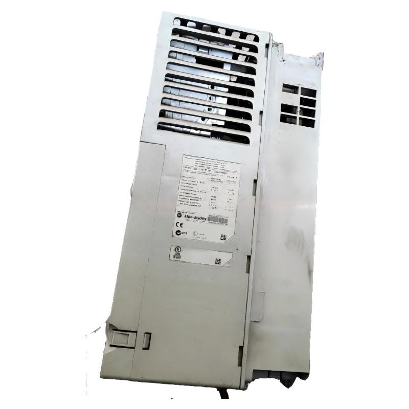
Motor Parameters and PowerFlex 753 Setup
Accurate motor data is essential for the Setup / Commissioning process.
The following information should be collected from the motor nameplate:
| Parameter | Configuration Basis |
|---|---|
| Motor rated voltage | Nameplate voltage |
| Motor rated current | Nameplate current |
| Motor rated frequency | Nameplate frequency |
| Motor rated speed | Nameplate RPM |
| Motor power | Nameplate kW |
| Acceleration time | Mechanical load |
| Deceleration time | Stopping requirements |
| Minimum frequency | Process requirements |
| Maximum frequency | Motor and machine limits |
| Start command source | Local or remote control |
| Speed reference source | Analog, network, or configured reference |
For applications requiring precise speed regulation, the selected motor-control method should be matched to the machine's operating characteristics.
A small pump, for example, may operate satisfactorily with a relatively simple speed-control arrangement. A machine requiring accurate low-speed torque may need a more detailed motor identification and control configuration.
PowerFlex 753 Commissioning and Operational Verification
Once the power circuit, motor connections, and parameters have been checked, perform commissioning under controlled conditions.
Start with the motor disconnected from the mechanical load where the machine design permits this arrangement.
Verify that the drive completes startup without active faults. Confirm the motor's rotation direction using a controlled low-speed command, then check output current and acceleration behavior.
For a nominal 2.1 A drive, an important commissioning check is whether actual motor current remains within the motor's nameplate rating during representative operating conditions.
Also verify:
Correct local and remote command selection.
Analog speed reference scaling.
PLC communication and feedback status.
Acceleration and deceleration response.
Motor thermal protection.
Fault reset and emergency-stop behavior.
The integrated braking transistor should not be confused with a complete braking resistor assembly. If the application requires dynamic braking, verify the external resistor selection and the manufacturer's permitted resistance and duty-cycle limits.
Field Commissioning Observation: Unstable Low-Speed Operation
During one small conveyor commissioning scenario, a 400V-class drive operated normally at medium speed but showed unstable motor behavior at low frequencies.
The initial suspicion was a defective output stage. However, the engineering investigation began with motor nameplate data and control configuration rather than immediate component replacement.
The technician reviewed the motor control mode, motor identification parameters, and speed reference scaling. The low-speed instability was associated with an unsuitable control configuration for the connected motor.
After correcting the motor data and control settings, the technician repeated the low-speed test under controlled loading conditions.
This illustrates why PowerFlex 753 commissioning should evaluate the motor and drive as one operating system.
Allen Bradley 20F11NC2P1JA0NNNNN Installation Search Keywords
Allen Bradley 20F11NC2P1JA0NNNNN installation guide
PowerFlex 753 400V AC drive wiring
20F11NC2P1JA0NNNNN setup and commissioning
Allen Bradley PowerFlex 753 2.1A drive configuration
PowerFlex 753 motor parameter setup
PowerFlex 753 PLC control wiring
PowerFlex 753 embedded I/O configuration
Installation and Commissioning Summary
Reliable operation of the Allen Bradley 20F11NC2P1JA0NNNNN depends on correct supply connections, compatible motor selection, proper cabinet cooling, and accurate System Configuration. Recording the final parameters and commissioning measurements provides a useful reference for future maintenance and troubleshooting.