Allen Bradley 20F11NC2P1JA0NNNNN PowerFlex 753 Motor Overcurrent Troubleshooting Guide
Time:2026-10-30 Browse: 2
Why the Allen Bradley 20F11NC2P1JA0NNNNN Trips on Motor Overcurrent
An Allen Bradley 20F11NC2P1JA0NNNNN PowerFlex 753 AC Drive that repeatedly trips during motor acceleration may be experiencing excessive motor current, incorrect motor parameter settings, or a mechanical overload condition. On this 400V-class, 2.1 A drive, even relatively small differences between configured motor data and actual operating requirements can affect current regulation and drive protection.
The PowerFlex 753 includes electronic motor protection and configurable motor-control functions. When an overcurrent fault occurs, the objective is to identify whether the excessive current originates from the motor, output wiring, mechanical load, or drive power section before attempting a repair.
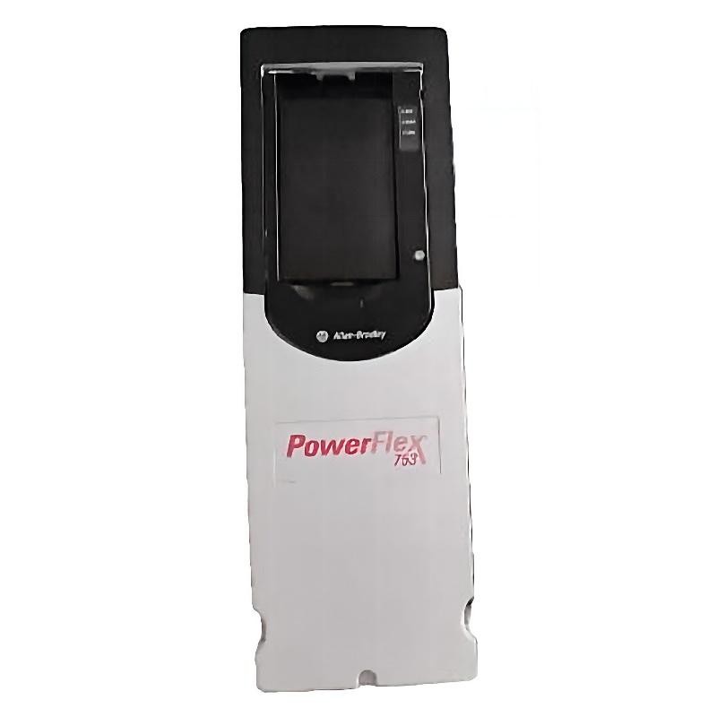
Recognizing PowerFlex 753 Motor Overcurrent Symptoms
Motor overcurrent faults do not always appear under the same operating conditions.
Typical patterns include:
The drive trips immediately after receiving a start command.
Motor current rises sharply during acceleration.
The drive operates normally without a mechanical load but trips under load.
Overcurrent faults occur intermittently during low-speed operation.
The motor produces abnormal noise or vibration before the drive stops.
Repeated fault resets temporarily restore operation but do not eliminate the problem.
The timing of the fault provides an important diagnostic clue.
An immediate trip may indicate an output short circuit or severe electrical problem. A trip occurring only during acceleration may instead point toward excessive load torque, unsuitable acceleration settings, or incorrect motor configuration.
PowerFlex 753 Fault Diagnosis: Separating Electrical and Mechanical Problems
The 20F11NC2P1JA0NNNNN has a nominal output current of 2.1 A. Therefore, the first diagnostic task is to compare the actual motor current requirements with the drive's applicable rating.
Do not use the drive's maximum current capability as a substitute for the motor nameplate rating.
The investigation should cover four areas.
Motor condition
Check winding resistance balance, insulation condition, bearing condition, and signs of mechanical damage. Significant differences between phase winding measurements may indicate a motor winding problem.
Output wiring
Inspect the U/T1, V/T2, and W/T3 connections for loose terminals, damaged insulation, incorrect connections, and possible phase-to-phase or phase-to-ground faults.
Mechanical load
Check whether the connected machine rotates freely. Worn bearings, obstructed pumps, conveyor jams, and excessive belt tension can increase the torque required during startup.
Drive configuration
Compare configured motor voltage, current, frequency, and speed against the motor nameplate. Incorrect motor data can interfere with the selected control strategy.
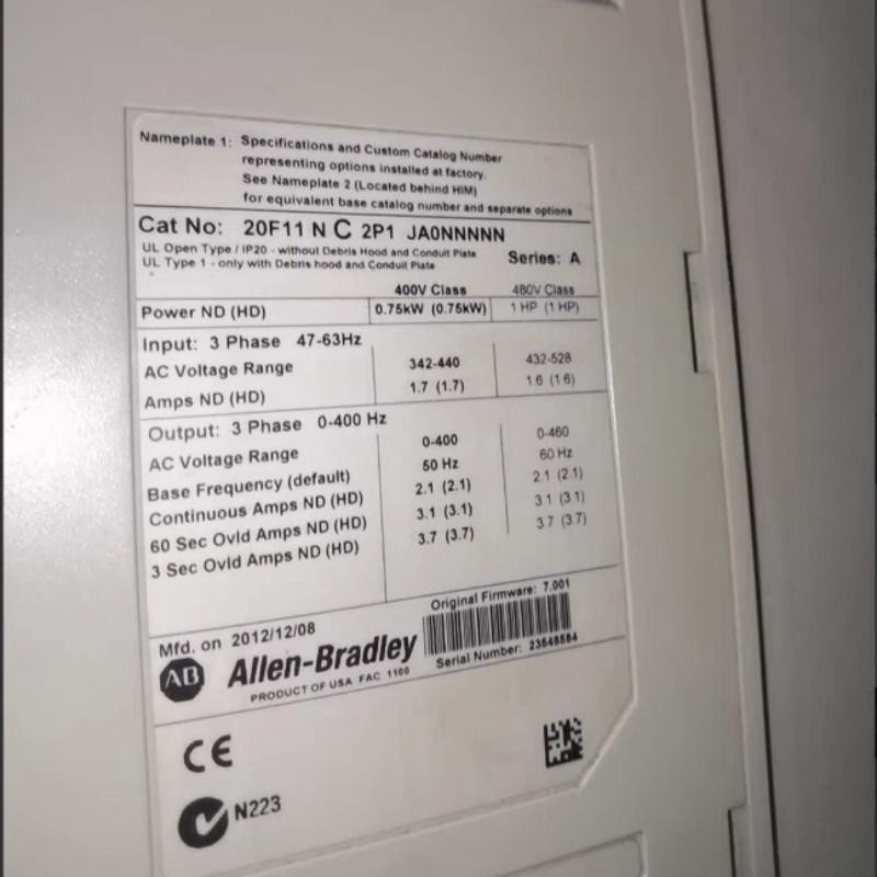
A Practical Investigation of Repeated PowerFlex 753 Acceleration Trips
Consider a small conveyor system using the 20F11NC2P1JA0NNNNN.
The machine starts successfully when unloaded but trips shortly after material is placed on the conveyor.
Instead of immediately replacing the drive, the maintenance engineer should compare the unloaded and loaded operating conditions.
The diagnostic reasoning proceeds as follows:
Record the drive fault code and fault history before resetting the system.
Compare motor current during unloaded and loaded operation.
Inspect conveyor bearings, rollers, belt tension, and gearbox condition.
Check motor nameplate data against the configured parameters.
Inspect output cable connections and motor winding condition.
Repeat the operating test under a controlled mechanical load.
If current increases significantly only when the conveyor is loaded, the mechanical system deserves particular attention.
If excessive current appears even without a mechanical load, the investigation should focus more closely on motor wiring, motor condition, and drive output behavior.
This comparison helps avoid unnecessary replacement of an otherwise functional PowerFlex 753.
Corrective Actions for Allen Bradley PowerFlex 753 Overcurrent Faults
Once the root cause has been identified, corrective work should target the specific problem.
| Diagnostic Finding | Recommended Action |
|---|---|
| Motor current setting incorrect | Re-enter verified motor nameplate data |
| Mechanical obstruction | Remove the obstruction and inspect affected components |
| Motor winding imbalance | Arrange motor testing and repair |
| Damaged output cable | Replace or repair the affected cable |
| Acceleration time too short | Adjust the acceleration profile within application limits |
| Motor unsuitable for drive rating | Reassess motor and drive compatibility |
| Suspected inverter damage | Perform qualified power-section diagnostics |
Increasing the acceleration time may help when the fault results from excessive acceleration demand. However, this adjustment should not be used to conceal a short circuit, motor defect, or mechanical obstruction.
PowerFlex 753 Output Stage Inspection and Repair
If the motor and output wiring pass their respective tests, attention can shift toward the drive's power section.
The inspection should include:
Output terminal condition.
Signs of overheating or discoloration.
Cooling fan operation.
Heatsink contamination.
DC bus condition.
Power semiconductor and gate-drive circuitry.
All electrical inspection must follow appropriate isolation and discharge procedures. The DC bus can retain dangerous voltage after incoming power is disconnected.
For suspected inverter faults, qualified technicians should use manufacturer-approved diagnostic procedures. Semiconductor testing should be performed with the drive isolated from external circuits and with sensitive electronic components protected.
The integrated braking transistor and EMC filter should also be considered when inspecting the power circuitry, but neither should be assumed to be the cause of a motor overcurrent fault without supporting evidence.
PowerFlex 753 Recovery Testing After Overcurrent Repair
After completing the repair, the drive should be returned to service through controlled testing.
Begin by checking the motor and cable connections. Confirm that the motor parameters remain correct and that the original fault has been cleared for a valid reason.
A recovery test should include:
Initial startup without abnormal current spikes.
Controlled acceleration.
Stable operation at several speed references.
Representative mechanical loading.
Controlled stopping.
Verification of PLC commands and drive status feedback.
Record motor current at different operating speeds and compare the measurements with the motor nameplate and expected application load.
Repeatedly resetting the drive without investigating the original fault is not an acceptable repair strategy.
Field Maintenance Case: Overcurrent During Loaded Conveyor Startup
In a representative industrial maintenance scenario, a small conveyor equipped with a PowerFlex 753 experienced repeated overcurrent trips after production material was introduced.
The drive operated normally during unloaded testing, which initially suggested that the electrical installation was functioning correctly.
The maintenance investigation then focused on the mechanical transmission. Inspection of the conveyor revealed excessive resistance in the driven assembly.
After correcting the mechanical problem, the technician repeated the loaded startup test and monitored motor current throughout acceleration.
The important diagnostic finding was the difference between unloaded and loaded current behavior. This helped distinguish a mechanical overload from a potential inverter failure.
For the 20F11NC2P1JA0NNNNN, this type of load comparison is particularly useful because its 2.1 A output rating requires careful attention to motor and application sizing.
Long-Tail Keywords for Allen Bradley 20F11NC2P1JA0NNNNN Troubleshooting
Allen Bradley 20F11NC2P1JA0NNNNN troubleshooting
PowerFlex 753 motor overcurrent fault diagnosis
20F11NC2P1JA0NNNNN drive repair
Allen Bradley PowerFlex 753 acceleration fault
PowerFlex 753 motor current troubleshooting
PowerFlex 753 inverter output fault inspection
400V PowerFlex 753 AC drive maintenance
Allen Bradley 2.1A variable frequency drive fault repair
Restoring PowerFlex 753 Drive Reliability
Motor overcurrent faults on the Allen Bradley 20F11NC2P1JA0NNNNN should be investigated through a combination of electrical measurements, motor parameter verification, and mechanical load inspection.
The most effective troubleshooting approach is to establish when the fault occurs, compare operating conditions, and eliminate possible causes systematically.
Corrective maintenance supported by recorded current measurements and controlled recovery testing helps restore reliable motor operation while reducing unnecessary drive replacements.