GE IC200ALG320B Analog Output Module Troubleshooting Guide (4–20 mA Output Fault Diagnosis)
Time:2026-11-02 Browse: 2
Why GE IC200ALG320B Analog Outputs Remain at 4 mA
When a GE IC200ALG320B analog output module remains at 4 mA despite changes in the PLC command, the problem may involve output scaling, field power, configuration, or an interrupted current loop. Replacing the module immediately is rarely the most efficient Fault Diagnosis approach.
The IC200ALG320B is a four-channel, 12-bit current output module in the VersaMax family. Its outputs operate in the nominal 4–20 mA range, making accurate current measurement more useful than relying on PLC register values alone.
This troubleshooting guide focuses on a specific failure pattern: an analog output that remains at its lower range despite a changing PLC command.
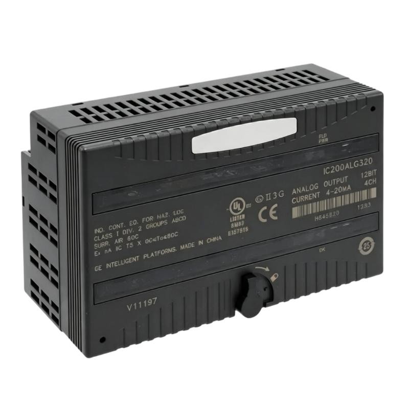
A Field Observation: The PLC Command Changes but the Current Does Not
Consider a hypothetical industrial commissioning case involving a GE VersaMax PLC controlling a modulating valve.
The operator reports that the valve remains near its minimum position. The PLC program appears to be running normally, and the output command changes from 25% to 75%.
However, the measured output current remains close to 4 mA.
Instead of immediately replacing the IC200ALG320B, the engineer separates the problem into three areas:
Whether the CPU is updating the analog output data.
Whether the module is receiving valid field-side power.
Whether the external current loop is electrically complete.
A useful initial measurement table would look like this:
| Test Condition | Expected Current | Observed Current |
|---|---|---|
| 25% command | 8 mA | 4 mA |
| 50% command | 12 mA | 4 mA |
| 75% command | 16 mA | 4 mA |
These values indicate that the output is not following the expected command. They do not, by themselves, establish whether the fault is inside the module.
GE IC200ALG320B Fault Diagnosis: Checking the Power Supply First
The first investigation should focus on the external power supply.
The IC200ALG320B requires external power for its field-side analog circuits. The recommended supply range is 18–30 VDC, including ripple.
Check the following:
Measure DC voltage directly at terminals A17 and A18.
Inspect the external supply fuse.
Check for loose connections at the carrier.
Verify that the FLD PWR LED is illuminated.
Measure supply voltage under operating load.
The green FLD PWR LED indicates the presence of field-side power. If this LED is off, investigate the external supply and associated wiring before examining PLC software.
A supply that measures 24 VDC without a connected load may still experience voltage collapse when several output channels operate simultaneously.
When the GE IC200ALG320B Output Remains at Minimum Current
If the field supply is normal, examine the PLC output data.
The module receives four words of analog output data from the CPU or network interface unit. An incorrect data assignment, scaling calculation, or output address can prevent the expected command from reaching the intended channel.
For a standard 4–20 mA control strategy, the relationship between percentage command and output current is:
I = 4 + (16 × Percentage / 100) mA
For example:
0% = 4 mA
50% = 12 mA
100% = 20 mA
Check whether the PLC program is writing to the correct output reference. Also confirm that the engineering-unit conversion is not limiting the output to its minimum value.
A practical diagnostic method is to monitor the raw output data while changing the command manually under controlled operating conditions.
If the raw value changes but the measured current does not, continue with electrical testing.
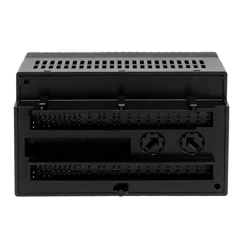
Investigating an Interrupted Current Loop on GE IC200ALG320B
Another possible cause is an open or incorrectly wired current loop.
The module uses individual output and return connections:
Channel 1: A2 and A3.
Channel 2: A5 and A6.
Channel 3: A8 and A9.
Channel 4: A11 and A12.
Inspect the corresponding field wiring and receiving-device terminals.
Particular attention should be given to terminal tightness, cable continuity, and incorrect connections introduced during instrument replacement.
The module supports a resistive load of up to 1250 ohms under suitable supply conditions. The actual permissible load must be calculated from the available external voltage.
A load exceeding the available output capability can cause abnormal current readings even when the PLC command is correct.
Distinguishing a Module Fault from a Configuration Problem
The IC200ALG320B provides two useful LED indications:
| Indicator | Meaning | Diagnostic Direction |
|---|---|---|
| OK | Backplane power present | Check carrier and backplane if off |
| FLD PWR | Field-side power present | Check external DC supply if off |
The module also supports diagnostics for loss of user-side power.
If both LEDs indicate normal power conditions, this does not automatically confirm that the analog output circuitry is healthy.
A more reliable approach is to compare the suspect channel against another channel using the same supply and a known compatible test load.
For example, if channel 1 remains at 4 mA while channel 2 responds correctly to equivalent PLC commands, inspect channel 1's wiring and load before concluding that the entire module has failed.
Because all four channels belong to one group and do not have channel-to-channel isolation, test arrangements must also account for the shared electrical architecture.
Recovery Procedure for GE IC200ALG320B Analog Output Problems
After identifying the cause, apply the appropriate corrective action.
| Identified Problem | Recommended Action |
|---|---|
| Missing external power | Restore the correct DC supply |
| Incorrect output address | Correct the PLC hardware configuration |
| Incorrect scaling | Recalculate the 4–20 mA conversion |
| Loose terminal connection | Repair and retighten the connection |
| Excessive load resistance | Verify load compatibility and supply capability |
| Incorrect jumper configuration | Set the required output default behavior |
| Persistent channel malfunction | Perform controlled module substitution and testing |
Before replacing the module, isolate the affected process and follow the site's electrical safety procedures.
If module replacement is necessary, verify compatibility with the existing VersaMax carrier and rack arrangement. Do not assume that every revision is interchangeable in every expansion-rack configuration.
Preventing Repeated GE IC200ALG320B Analog Output Failures
Long-term reliability depends on more than replacing defective components.
For industrial applications, record the following during routine maintenance:
External DC supply voltage.
Actual output current at representative operating points.
Terminal condition and wiring continuity.
PLC output scaling and channel assignments.
FLD PWR and OK LED status.
Output default jumper configuration.
It is also useful to record baseline measurements during commissioning. These values provide a reference when troubleshooting future signal deviations.
Where the module controls critical process equipment, verify that the selected Hold Last State or 4 mA default behavior is appropriate for the actual process safety requirements.
Long-Tail Keywords for GE IC200ALG320B Troubleshooting
GE IC200ALG320B analog output module troubleshooting
IC200ALG320B 4–20 mA output fault diagnosis
GE VersaMax analog output stuck at 4 mA
IC200ALG320B FLD PWR LED fault
GE IC200ALG320B external power supply troubleshooting
IC200ALG320B PLC analog output signal problem
GE IC200ALG320B channel output testing and repair
Technical Reference and Documentation
For detailed terminal assignments, output characteristics, jumper selection, and installation requirements, consult the GE VersaMax technical documentation:
VersaMax Analog Output Modules, GFK-2527.
VersaMax Modules, Power Supplies, and Carriers User's Manual, GFK-1504.
Always verify the hardware revision and applicable documentation before carrying out field modifications.