GE IC200ALG320B Analog Output Module Installation Guide (4–20 mA Wiring & Commissioning)
Time:2026-11-02 Browse: 2
Understanding the GE IC200ALG320B Analog Output Module
The GE IC200ALG320B analog output module requires correct field power, terminal wiring, and output configuration to deliver stable 4–20 mA control signals. Designed for the GE Fanuc VersaMax PLC platform, this 12-bit current output module provides four independent single-ended channels for controlling field devices such as control valves, variable-speed drives, and other current-operated equipment.
During installation, particular attention should be given to the external DC supply and the output return connections. Unlike modules that obtain all operating power from the backplane, the IC200ALG320B requires an external supply for its analog output circuits.
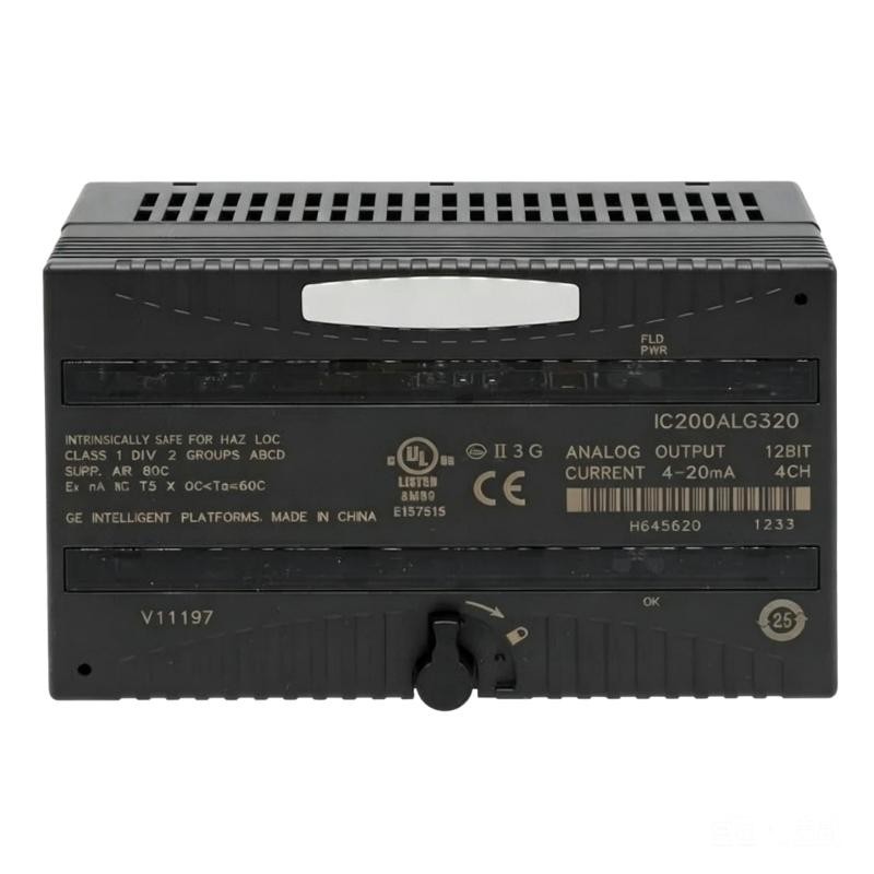
GE IC200ALG320B Module Architecture and Operating Characteristics
The module provides four current-sourcing analog outputs, with a nominal operating range of 4–20 mA.
| Parameter | Specification |
|---|---|
| Product model | IC200ALG320B |
| Product family | GE Fanuc VersaMax |
| Module type | 12-bit Analog Output Module |
| Number of channels | 4 |
| Output signal | 4–20 mA |
| Output resolution | 4 μA |
| External supply | 18–30 VDC |
| Alternative supply range | 9.6–15 VDC |
| Maximum module update rate | 0.3 ms |
| Backplane consumption | 50 mA maximum at 5 VDC |
| Isolation | 250 VAC continuous; 1500 VAC for 1 minute |
| Diagnostics | Loss of user-side power |
The four channels share one output group, and there is no channel-to-channel isolation. This distinction matters when designing grounding arrangements and connecting equipment supplied from different electrical sources.
Installation Preparation: Power, Carrier, and Field Wiring
Before mounting the GE IC200ALG320B, verify that the selected VersaMax carrier is compatible with the module revision. Revision B is particularly relevant when installing the module in an expansion rack; the manufacturer identifies revision C or later as the minimum requirement for expansion-rack installations.
Prepare the following items:
Compatible VersaMax I/O carrier.
Regulated external DC power supply.
Shielded twisted-pair signal cables.
Terminal identification labels.
Digital multimeter for checking supply voltage and output current.
The recommended external supply range is 18–30 VDC, including ripple. A separate 9.6–15 VDC operating range is also specified for 12 V applications.
For a 24 VDC installation, measure the voltage at the module-side terminals rather than relying exclusively on the power supply display. Voltage drops along long cable runs can affect the available output compliance.
GE IC200ALG320B Terminal Wiring and Signal Connections
The field wiring arrangement uses dedicated output and return terminals.
| Terminal | Function |
|---|---|
| A2 | I OUT 1 |
| A3 | RET 1 |
| A5 | I OUT 2 |
| A6 | RET 2 |
| A8 | I OUT 3 |
| A9 | RET 3 |
| A11 | I OUT 4 |
| A12 | RET 4 |
| A17 | DC− |
| A18 | DC+ |
| B2, B4, B6, B8, B10, B12 | Shield termination points |
Use the appropriate carrier wiring diagram when identifying physical terminal positions. The terminal arrangement varies with carrier configuration.
For a typical control-valve application, connect the selected current output to the receiving device's positive signal terminal and connect the corresponding return to its signal return.
Avoid combining unrelated output returns or grounding the shield at multiple points without checking the plant grounding design.
Shielded twisted-pair cable is recommended for analog connections. Proper shield termination helps reduce electromagnetic interference from motor cables, contactors, and variable-frequency drives.
System Configuration and Output Default Selection
The GE IC200ALG320B supports two output behaviors when communication or backplane power is interrupted:
Hold Last State: retains the last commanded output value.
4 mA Default: drives the configured default output current.
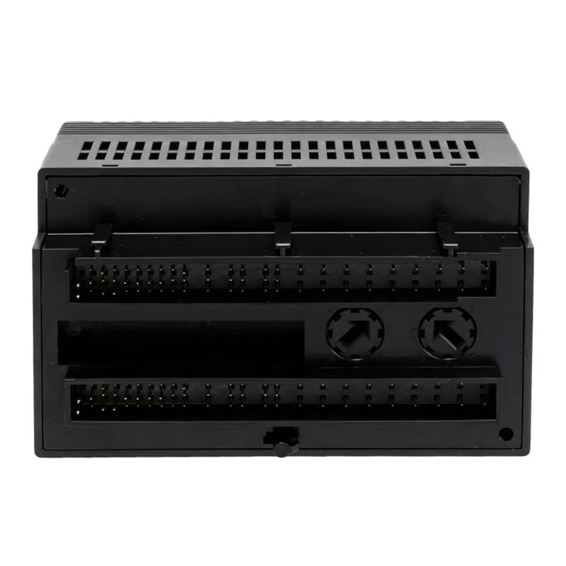
The module uses jumper selection to determine the output behavior. With no jumper installed, the outputs retain their last commanded values when backplane power or communication is interrupted.
This selection should be evaluated against the process safety requirements.
For example, a control valve that must remain in its previous position during a short communication interruption may require a different strategy from a valve that should move toward a predefined safe operating condition.
The output default is not a substitute for an independent emergency shutdown strategy.
GE IC200ALG320B Setup and Commissioning Verification
Once the wiring and configuration are complete, perform a controlled commissioning test.
First, verify that the green OK LED indicates backplane power is present. Next, check the FLD PWR LED to confirm that external field power is available.
A practical output test can use the following reference values:
| PLC Command | Expected Output |
|---|---|
| 0% | 4 mA |
| 25% | 8 mA |
| 50% | 12 mA |
| 75% | 16 mA |
| 100% | 20 mA |
Use a calibrated loop meter to measure the actual current. Where possible, test with the final field device connected because the load resistance affects output performance.
The maximum resistive load is determined by the external supply voltage:
RL(max) = (V external supply − 4 V) / 20.38 mA
For a 24 VDC supply, the theoretical maximum resistive load is approximately 981 ohms.
If the measured current differs from the PLC command, check the output scaling, load resistance, wiring polarity, and external supply before considering module replacement.
Field Commissioning Notes for GE VersaMax Analog Outputs
One common commissioning situation involves a PLC displaying a correct analog command while the receiving control valve remains stationary.
The initial assumption may be that the analog output module is defective. However, a more useful diagnostic approach is to measure the actual loop current independently.
For example, if the PLC commands 12 mA but the field instrument receives only 4 mA, inspect the loop wiring and field power first. A disconnected return conductor or an incorrectly connected load can interrupt the current path.
The IC200ALG320B also reports loss of user-side power, making the FLD PWR indication an important part of the initial inspection.
These checks help distinguish a genuine hardware fault from an installation or configuration problem.
Long-Tail Keywords for GE IC200ALG320B Installation
GE IC200ALG320B analog output module installation guide
GE IC200ALG320B 4–20 mA wiring diagram
GE VersaMax IC200ALG320B PLC setup and commissioning
IC200ALG320B external power supply requirements
GE IC200ALG320B analog current output configuration
IC200ALG320B field wiring and terminal connections