GE IC200ALG264H Analog Input Module Troubleshooting Guide (Signal Fluctuation & Fault Diagnosis)
Time:2026-11-02 Browse: 2
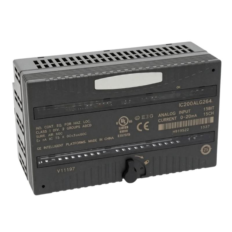
Why Does the GE IC200ALG264H Analog Input Module Produce Unstable Readings?
GE IC200ALG264H analog input instability is not necessarily a sign of module failure. In VersaMax PLC installations, fluctuating current readings can result from poor signal grounding, electrical interference, unstable transmitter output, or an incorrect common-return connection.
The IC200ALG264H processes 15 single-ended current inputs through a shared common reference. Consequently, a problem affecting the field wiring or common-return arrangement may influence more than one channel.
Effective GE IC200ALG264H Troubleshooting should begin by comparing the actual field current with the PLC input data. Replacing the Analog Input Module before performing this comparison can lead to unnecessary maintenance costs.
GE IC200ALG264H Signal Fluctuation: Understanding the Fault Pattern
Consider a typical industrial monitoring arrangement in which several 4–20 mA transmitters are connected to the same VersaMax I/O system.
Operators may report the following symptoms:
Pressure readings fluctuate without corresponding process changes.
Several analog channels show intermittent variations.
HMI values differ from local transmitter displays.
The PLC input remains unstable even when the process is steady.
Signal readings become less reliable when nearby motors or drives operate.
The first diagnostic question is whether the instability originates from the transmitter, the wiring, or the module.
An engineer should not immediately conclude that the IC200ALG264H has a defective analog-to-digital converter.
GE IC200ALG264H Fault Diagnosis: Separating Field Signals from PLC Data
A practical Fault Diagnosis process compares three measurement points:
The transmitter's actual current output.
The current measured at the module input terminals.
The corresponding PLC input value.
The comparison helps identify where the signal begins to deviate.
For example:
| Measurement Point | Example Reading |
|---|---|
| Transmitter output | 12.00 mA |
| Module terminal measurement | 11.98 mA |
| Expected PLC engineering value | 50% |
| Actual PLC engineering value | 49.9% |
Small differences may fall within normal measurement tolerances.
However, if the transmitter produces a stable 12 mA signal while the PLC value fluctuates significantly, attention should shift toward the field wiring, grounding, configuration, and module input circuitry.
Use a calibrated loop meter and suitable electrical test equipment. Measurements must be performed by qualified personnel using the site's electrical isolation and safety procedures.
GE IC200ALG264H Troubleshooting: Common Causes of Unstable Analog Signals
Shared Common Return Problems
The IC200ALG264H uses 15 single-ended channels with one common return.
Loose terminal connections, poor return continuity, or an unsuitable grounding arrangement can introduce unwanted voltage differences into the measurement circuit.
When several channels fluctuate simultaneously, inspect the shared return path before investigating individual input channels.
Electrical Interference from Industrial Equipment
Analog current loops are generally resistant to electrical interference, but poor cable routing can still introduce unwanted noise.
Particular attention should be given to cables installed alongside:
Variable-frequency drive output cables.
High-current motor conductors.
Switching power supplies.
Electromagnetic contactors.
High-frequency switching equipment.
Inspect the shield termination and cable routing. Shielded twisted-pair wiring is recommended, with the shield grounded at the source device or, where appropriate, at the I/O module through an auxiliary I/O terminal.
Avoid creating unintended multiple grounding paths.
Incorrect Input Range Configuration
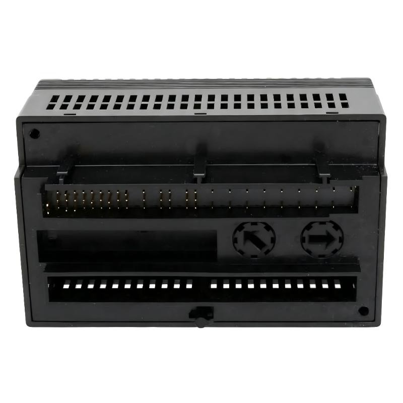
The IC200ALG264H supports two current ranges.
| Operating Range | Jumper Configuration |
|---|---|
| 4–20 mA | No jumper installed |
| 0–20 mA | Jumper installed between A16 and A17 |
If the physical jumper setting does not match the PLC System Configuration, the displayed engineering values may be incorrect.
Confirm the hardware setting before changing the PLC scaling logic.
An Engineering Diagnostic Scenario: GE IC200ALG264H Analog Signal Drift
Consider a representative field troubleshooting scenario involving a pressure monitoring system.
The operator reports that the HMI pressure value moves intermittently even though the process appears stable.
The maintenance engineer performs the following investigation:
Initial observation
The affected PLC channel shows fluctuating engineering values. The transmitter's local display remains stable.
Signal verification
A calibrated loop meter is connected in the appropriate measurement arrangement. The transmitter output is found to be stable at approximately 12 mA.
Wiring inspection
The engineer discovers that the analog cable shield and common-return arrangement require correction. The signal cable also runs close to a motor power cable.
Corrective action
The cable routing and shield termination are reviewed, the common-return connections are inspected, and the system is tested again under normal operating conditions.
Final validation
The measured current and PLC engineering value are compared over a suitable observation period. Stable agreement between the two measurements confirms that the signal path is operating as expected.
This is an illustrative engineering case, not a claim of a verified customer repair record. The actual root cause must always be established through site measurements.
GE IC200ALG264H Open-Wire and Internal Power Fault Diagnostics
Signal fluctuation is not the only condition worth investigating.
The module also provides specific diagnostic functions.
Open-wire detection
Open-wire diagnostics are available for 4–20 mA input signals. If a loop becomes disconnected, the PLC may report an open-wire condition for the affected channel.
Check:
Transmitter power supply.
Positive and negative loop connections.
Terminal tightness.
Cable continuity.
Field instrument output terminals.
Open-wire detection is not available in the same manner when the module is configured for 0–20 mA operation.
Loss of internal power
The module reports a Loss of Internal Power fault for field-side circuits.
When this diagnostic appears, investigate the relevant carrier connections, field-side power arrangements, and module operating conditions rather than assuming that the PLC backplane supply is the only possible cause.
OK LED abnormal status
If the green OK LED does not indicate normal operation, inspect backplane power, module seating, configuration recognition, and the carrier connection.
GE IC200ALG264H Module Repair: When Should Hardware Replacement Be Considered?
Hardware replacement should be considered only after the external signal path has been checked.
A useful diagnostic sequence is:
| Diagnostic Finding | Recommended Investigation |
|---|---|
| One channel fluctuates | Inspect the individual transmitter and wiring |
| Multiple channels fluctuate | Inspect shared return and grounding |
| All values are incorrect | Verify input range and PLC scaling |
| Open-wire diagnostic appears | Check the corresponding current loop |
| Internal power fault appears | Investigate field-side power circuitry |
| PLC does not recognize module | Check carrier seating and hardware configuration |
| Readings remain incorrect with verified signals | Investigate possible module hardware damage |
If a suspected module failure remains after these checks, remove the unit according to the plant's isolation procedures and arrange qualified bench testing.
When replacing an IC200ALG264H, verify the complete catalog number, hardware revision, carrier compatibility, and existing configuration.
A replacement from the same IC200ALG264 family should not be selected solely because its housing and terminal layout appear identical.
GE IC200ALG264H Troubleshooting: Signal Verification and Recovery
After corrective work, perform a controlled validation rather than relying only on the absence of alarms.
A suitable verification procedure includes:
Confirming that the selected input range matches the carrier jumper.
Applying known current signals to representative channels.
Checking the PLC's raw input values.
Verifying the engineering scaling.
Observing readings during normal equipment operation.
Confirming that diagnostic conditions have cleared.
Recording the final measurements for maintenance history.
The module has a nominal 7.5 ms update rate and a 24 Hz ±20% filter response. These characteristics should be considered when evaluating short-duration signal variations.
A signal that changes briefly may reflect actual process behavior, electrical interference, or the measurement system's response. The timing and magnitude of the variation are important diagnostic evidence.
GE IC200ALG264H Troubleshooting Guide: Long-Tail Search Keywords
The following technical search terms are relevant to engineers maintaining GE VersaMax analog input systems:
GE IC200ALG264H troubleshooting guide
IC200ALG264H analog input signal fluctuation
GE VersaMax 15-channel analog input fault diagnosis
IC200ALG264H 4–20 mA open-wire error
GE IC200ALG264H internal power fault
IC200ALG264H PLC input reading incorrect
GE IC200ALG264H analog current input repair
IC200ALG264H common return wiring problems
GE VersaMax analog input module signal instability
Accurate fault identification requires separating field instrument problems from wiring defects and actual module failures. A structured Troubleshooting approach helps engineers restore reliable analog signal acquisition while avoiding unnecessary component replacement.