GE IC200ALG264H Analog Input Module Installation Guide (Wiring & Commissioning)
Time:2026-11-02 Browse: 2
Understanding the GE IC200ALG264H Analog Input Module
The GE IC200ALG264H analog input module is designed to acquire multiple industrial current signals and transfer measurement data to a VersaMax PLC system. With 15 single-ended input channels and 15-bit resolution, the module supports both 4–20 mA and 0–20 mA signals, making it suitable for monitoring pressure transmitters, flow meters, temperature transmitters, and other process instruments.
A successful GE IC200ALG264H Installation Guide should focus on three critical areas: input range selection, common-return wiring, and PLC System Configuration. Incorrect jumper settings or inconsistent signal grounding can cause inaccurate measurements even when the module itself is operating normally.
The IC200ALG264H is a hardware revision of the IC200ALG264 family. Revision H introduced a labeling change without changing the module's material, process, form, fit, or functionality.
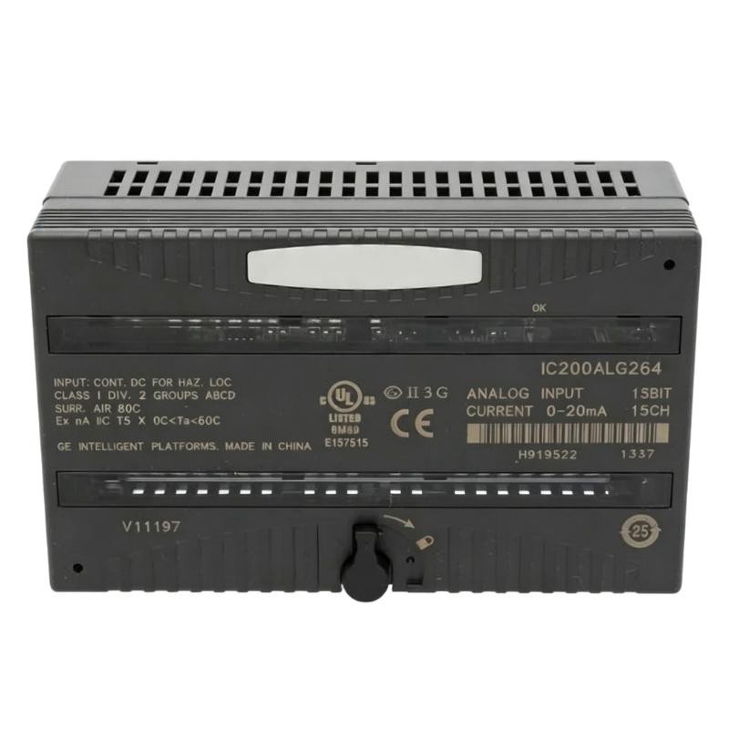
GE IC200ALG264H Module Architecture and Electrical Characteristics
Before starting installation, engineers should understand how the module handles field signals.
| Parameter | Specification |
|---|---|
| Product Series | GE VersaMax |
| Model | IC200ALG264H |
| Module Type | Analog Current Input Module |
| Input Channels | 15 single-ended |
| Input Range | 4–20 mA / 0–20 mA |
| Resolution | 15-bit |
| Input Impedance | 100 Ω |
| Typical Accuracy at 25°C | ±0.3% of full scale |
| Maximum Accuracy Error at 25°C | ±0.5% of full scale |
| Maximum Accuracy Error at 0–60°C | ±1% of full scale |
| Update Rate | 7.5 ms |
| Filter Response | 24 Hz ±20% |
| Backplane Power Consumption | 5 VDC, 100 mA maximum |
All 15 channels share one common return. They are not individually isolated from one another, so the field wiring design must account for the common reference.
Installation Preparation for GE IC200ALG264H PLC Systems
The first commissioning decision is whether the field instruments use a 4–20 mA or 0–20 mA signal.
This matters because the input range is selected through the carrier terminal jumper rather than through software alone.
Before installing the module, check:
The exact module identification and revision.
Compatibility of the VersaMax carrier and PLC hardware.
Available backplane current capacity.
The output configuration of each connected transmitter.
The grounding arrangement of the field instrument cables.
The required input range for all connected channels.
The IC200ALG264H receives its operating power from the PLC backplane. However, external power must be provided for the field transceivers where required.
Using shielded twisted-pair cables is recommended for analog signal transmission, particularly in installations containing variable-frequency drives, contactors, and other electrical noise sources.
GE IC200ALG264H Wiring and Current Range Selection
The module uses carrier terminal connections for its analog inputs.
The main terminal assignments are:
| Terminal | Function |
|---|---|
| A1–A15 | Current inputs I1–I15 |
| A16 | Range jumper connection |
| A17 | Return (common) |
| A18 | Not connected |
| B1–B18 | No connection |
The input range is selected as follows:
4–20 mA configuration
Leave the range jumper uninstalled. This is the default operating configuration.
0–20 mA configuration
Install a jumper between terminals A16 and A17.
A common installation mistake is to configure the transmitter for 4–20 mA while installing the carrier jumper for 0–20 mA. Although the module may continue receiving current, the resulting engineering values will not match the PLC scaling configuration.
For current-loop wiring, verify the transmitter polarity and return path before connecting multiple instruments to the shared common terminal.
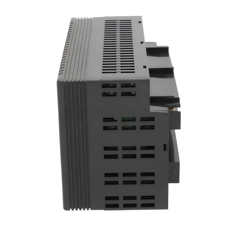
GE IC200ALG264H PLC Setup and Commissioning Procedure
After completing the physical wiring, the next task is to establish the correct relationship between the hardware configuration and PLC application.
In the programming environment, verify that the installed module is recognized as the appropriate VersaMax analog current input module.
The module identification depends on the selected hardware range:
4–20 mA: FFFFB50F
0–20 mA: FFFFB40F
The PLC configuration must match the physical jumper arrangement.
Once the module is recognized, verify the input data allocation. The IC200ALG264H provides 15 words of analog input data, corresponding to its 15 input channels.
A useful commissioning check is to apply known current values to a selected channel and compare the PLC reading against the expected conversion.
For example, when testing a 4–20 mA channel:
| Input Current | Expected Signal Position |
|---|---|
| 4 mA | 0% |
| 8 mA | 25% |
| 12 mA | 50% |
| 16 mA | 75% |
| 20 mA | 100% |
These percentages represent normalized engineering values rather than the raw PLC register counts.
A basic scaling expression is:
Engineering Value = (Measured Current − 4) / 16 × Engineering Range
For a pressure transmitter configured for 0–10 bar, a measured current of 12 mA should correspond to approximately 5 bar.
GE IC200ALG264H Installation Validation and Acceptance
The green OK LED provides an important indication of module operating status. Its normal operation depends on backplane power, internally generated field-side power, valid configuration, and module recognition.
During commissioning, check the following:
The module is correctly seated in its carrier.
The OK LED indicates normal operation.
All connected transmitters produce valid current signals.
The PLC recognizes the correct module configuration.
Input values change consistently with the applied current.
No unexpected open-wire or internal power diagnostics are present.
The HMI displays the correct engineering values.
For a more reliable acceptance test, record the measured current, PLC raw value, scaled engineering value, and channel number.
This information provides a useful baseline for subsequent maintenance and Fault Diagnosis.
GE IC200ALG264H Installation Guide: Long-Tail Technical Search Terms
Engineers searching for GE IC200ALG264H installation information may also need guidance on:
GE IC200ALG264H analog input module wiring diagram
IC200ALG264H 4–20 mA jumper configuration
GE VersaMax 15-channel current input module setup
IC200ALG264H PLC input scaling configuration
GE IC200ALG264H commissioning and signal testing
IC200ALG264H carrier terminal assignments
GE VersaMax analog input module compatibility
Correct hardware configuration, signal wiring, and PLC scaling are essential for achieving reliable analog data acquisition in an industrial control system.