Honeywell 51304638-600 Analog Output Isolator Installation Guide (Setup & Commissioning)
Time:2026-11-03 Browse: 1
The Honeywell 51304638-600 analog output electrical isolator is designed to provide galvanic isolation in industrial analog output circuits. Correct installation is important for maintaining signal integrity, reducing unwanted electrical interference, and ensuring reliable communication between the control system and connected field devices. Before commissioning, engineers should verify the hardware revision, system compatibility, terminal assignments, and electrical characteristics against the applicable Honeywell documentation.
Understanding the Honeywell 51304638-600 Analog Output Isolator
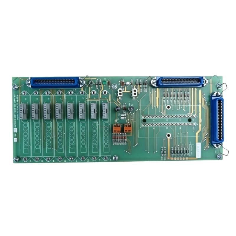
The 51304638-600 is identified as an analog output galvanic isolator. Its primary function is to electrically separate compatible control-system output circuits from field-side connections.
In process automation environments, differences in ground potential between control cabinets and field equipment can introduce unwanted current into analog signal paths. This may result in output fluctuations, unstable actuator responses, or inconsistent control performance.
The Honeywell isolator helps address these conditions by providing electrical separation between connected circuits.
Typical application areas include:
Industrial process control systems
Analog output signal interfaces
Control valve and actuator signal circuits
Distributed control system (DCS) installations
Industrial electrical isolation applications
The component should be treated as an analog signal interface rather than a standalone PLC Controller. The actual control signal is generated by the associated controller or output module.
Installation Preparation for Honeywell 51304638-600
Before beginning the installation, confirm that the replacement component matches the existing system configuration.
Several details deserve particular attention.
Hardware identification
Check the complete part number, revision marking, connector arrangement, and physical condition. Do not assume that components with similar Honeywell part numbers have identical electrical characteristics.
System Configuration
Confirm the intended controller platform, mounting assembly, and associated analog output interface. Honeywell control systems may use different termination arrangements depending on the installed hardware generation.
Electrical compatibility
Review the approved documentation for:
Analog output signal type and range
Field-side electrical requirements
Permitted load impedance
Isolation characteristics
Power supply requirements
Terminal assignments
A 4–20 mA signal is common in industrial process control, but its presence in the surrounding system does not automatically establish the supported range of every isolator revision.
Cabinet inspection
Inspect the mounting location for dust, moisture, corrosion, damaged connectors, and signs of overheating. Verify that the cabinet grounding arrangement is consistent with the plant electrical design.
Honeywell 51304638-600 Wiring and Installation Considerations
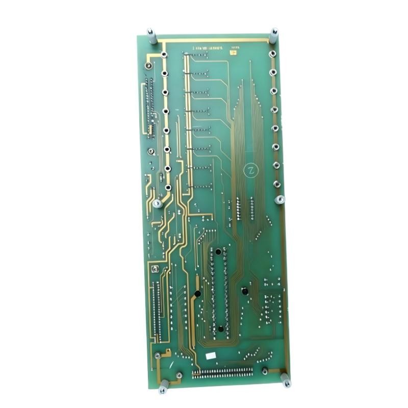
The wiring arrangement should follow the approved system drawing rather than a generic analog isolator diagram.
Identify the control-system side and field-device side before making connections. Keep analog signal wiring separated from motor power cables, contactor wiring, and other sources of electromagnetic interference.
For installations involving control valves or positioners, pay attention to the complete current loop. A correct controller output does not guarantee that the field device will receive the intended signal if the wiring or termination arrangement is incorrect.
Practical installation considerations include:
Use the specified conductor size and terminal hardware.
Maintain correct polarity where applicable.
Avoid unnecessary cable splices.
Keep shield connections consistent with the plant grounding standard.
Check terminal tightness using the specified torque.
Do not connect unverified external power sources to the isolator.
Before inserting or removing the assembly, follow the applicable cabinet isolation procedure. Never assume that hot swapping is supported without confirmation from the system documentation.
Honeywell 51304638-600 Setup and Commissioning Procedure
Commissioning should establish that the controller command, isolation interface, and field-device response are consistent.
Start with the controller configuration. Confirm that the associated PLC Controller or DCS output channel is configured for the correct signal type and engineering range.
Next, verify the physical connections and inspect the termination assembly.
Where the approved design uses a 4–20 mA output, a useful reference relationship is:
| Command | Expected current |
|---|---|
| 0% | 4 mA |
| 25% | 8 mA |
| 50% | 12 mA |
| 75% | 16 mA |
| 100% | 20 mA |
These values describe a standard 4–20 mA scaling example, not independently verified specifications for every 51304638-600 installation.
Using an approved loop calibrator or suitable meter, compare the commanded output with the measured signal at the designated test points.
If the controller commands 50% but the field device receives a substantially different current, investigate the signal path before replacing hardware.
Field Commissioning Example: Analog Output Verification
Consider a representative commissioning scenario involving an isolated analog output connected to a control valve positioner.
The controller indicates a 50% command. However, the valve position feedback does not correspond to the requested operating point.
The engineer first checks the output value in the control system. The displayed command is stable.
The next inspection focuses on the field wiring, terminal connections, and signal measurement points. A loose termination is discovered during the inspection.
After correcting the connection, the engineer repeats the output verification and confirms that the measured current follows the commanded value.
This example illustrates an important commissioning principle: an abnormal field response does not automatically indicate an isolator failure. The controller, termination assembly, wiring, and actuator must be evaluated as one signal chain.
Honeywell 51304638-600 Installation Validation
Before returning the equipment to normal operation, complete a final validation.
Confirm that the installed part number and revision are correct.
Verify the mechanical installation and connector engagement.
Check all wiring against the approved drawings.
Confirm that the analog output follows the controller command.
Verify field-device response across the required operating range.
Review system alarms and diagnostic messages.
Record the commissioning measurements.
Documenting the initial signal measurements is particularly useful for future maintenance. It provides a reference when investigating subsequent signal deviations or intermittent faults.
Long-Tail Keywords for Honeywell 51304638-600 Installation
The following search phrases are relevant to installation and industrial maintenance applications:
Honeywell 51304638-600 installation guide
Honeywell 51304638-600 analog output isolator setup
51304638-600 commissioning procedure
Honeywell analog output galvanic isolator wiring
Honeywell 51304638-600 system configuration
Industrial analog output signal isolation
Honeywell DCS analog output installation
Analog output isolator commissioning and testing
Frequently Asked Questions About Honeywell 51304638-600
What is the main function of the Honeywell 51304638-600?
It is identified as an analog output electrical isolator used to provide galvanic separation in compatible industrial control signal circuits.
Can the 51304638-600 be installed without checking the system configuration?
No. The hardware revision, mounting arrangement, electrical characteristics, and terminal assignments should be verified before installation.
Does the isolator generate the analog output command?
No. The controller or associated output module generates the command. The isolator provides the designated electrical isolation function.
How can installation problems be identified?
Compare the controller output command with the measured signal at approved test points. Inspect wiring, connections, grounding, and field-device compatibility if the measurements do not agree.
What should be recorded during commissioning?
Record the hardware identification, system configuration, measured signal values, field-device response, and any corrective actions.
Conclusion
A reliable Honeywell 51304638-600 installation depends on correct hardware identification, compatible system configuration, proper wiring, and measured commissioning results. Engineers should verify the entire analog output signal path instead of treating the isolator as an independent component. This approach helps reduce unnecessary replacements and improves long-term process control reliability.