Honeywell 51304638-600 Analog Output Fault Troubleshooting (Signal Instability Diagnosis)
Time:2026-11-03 Browse: 1
Honeywell 51304638-600 analog output instability can result from poor field connections, grounding differences, incorrect signal configuration, or problems elsewhere in the control loop. When a connected actuator receives an inconsistent command, replacing the isolator should not be the first response. A systematic Fault Diagnosis should establish whether the abnormal signal originates from the controller, isolation assembly, field wiring, or receiving device.
When Honeywell 51304638-600 Output Signals Become Unstable
An intermittent analog output fault can be difficult to identify because the control system may continue operating without reporting a permanent hardware alarm.
Typical observations include:
The field actuator moves despite a constant controller command.
The measured analog output fluctuates unexpectedly.
A control valve responds inconsistently to small setpoint changes.
The output signal becomes unstable when nearby equipment starts.
The control system indicates a normal command while the field device behaves abnormally.
These symptoms do not necessarily mean that the 51304638-600 has failed.
The first diagnostic question should be whether the controller command itself is changing or whether the signal becomes abnormal after leaving the output channel.
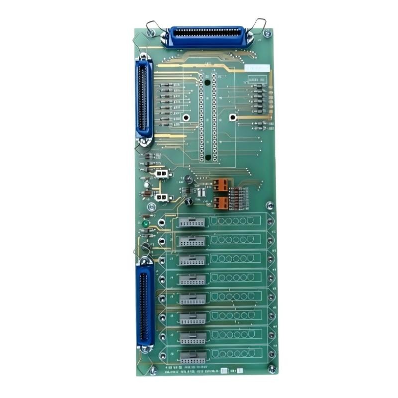
Fault Diagnosis: Separating Controller Problems from Isolator Problems
A useful troubleshooting method is to divide the complete signal path into individual sections.
The investigation should cover:
PLC Controller or DCS output command.
Associated analog output module.
Honeywell 51304638-600 isolation assembly.
Field wiring and termination points.
Connected actuator or positioner.
Compare the available measurements at each approved test location.
For example, if the control system maintains a stable 12 mA command but the receiving device experiences an intermittent signal, the fault is likely somewhere downstream of the command-generation stage.
However, this observation alone cannot prove that the isolator is defective. Wiring resistance, loose terminals, grounding arrangements, and field-device loading must also be considered.
A Field-Style Investigation: Output Fluctuation During Equipment Operation
Consider a representative industrial troubleshooting scenario.
An analog output channel controls a field actuator. During normal operation, the controller command remains at approximately 50%. However, the actuator occasionally changes position without a corresponding command adjustment.
The maintenance team initially suspects the analog output isolator.
Instead of immediately replacing it, the engineer compares the controller-side command with the measured field-side signal.
For a standard 4–20 mA application, a 50% command corresponds to 12 mA.
The investigation follows this logic:
Observation: The control-system command remains stable.
Inspection: The field wiring is examined for loose connections and damaged insulation.
Measurement: Current is checked using an approved measurement method and suitable test points.
Isolation of the fault: The engineer investigates whether the abnormal behavior appears before or after the isolation interface.
A representative test record might show a stable controller-side reference near 12 mA while the receiving-side measurement intermittently changes. These are illustrative diagnostic values, not verified measurements from an actual Honeywell 51304638-600 service case.
If the deviation disappears after correcting a loose field termination, replacing the isolator would have been unnecessary.
The key engineering lesson is to locate the point where the signal first becomes abnormal.
Why Honeywell 51304638-600 Analog Output Signals May Become Unstable
Several failure patterns should be considered during investigation.
Loose field terminals
Mechanical vibration and repeated cabinet maintenance can gradually affect terminal connections. An intermittent connection may produce unstable current transmission or unexpected actuator behavior.
Inspect the termination points and check the specified tightening requirements.
Ground potential differences
Different grounding references between the control cabinet and field equipment can introduce unwanted electrical effects.
Galvanic isolation is intended to reduce direct electrical interaction between separated circuits, but it does not eliminate the need for correct grounding and shielding practices.
Electromagnetic interference
Analog signal cables installed alongside motor feeders, variable-frequency drives, or contactor circuits may experience electrical interference.
Inspect cable routing and shielding before concluding that the isolator has failed.
Incorrect System Configuration
An incorrect output range or channel configuration can create a mismatch between the controller command and field-device response.
Verify the configured signal type, scaling, and associated hardware assignments.
Internal isolator damage
If the controller output and external wiring are verified, but the signal remains abnormal across the isolation interface, internal hardware damage becomes a stronger possibility.
A confirmed diagnosis requires approved testing or substitution with a known-good compatible assembly.
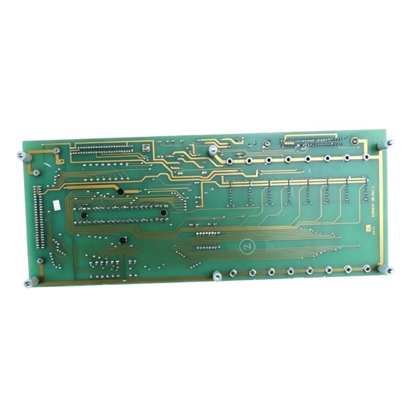
Troubleshooting a Missing Analog Output
A completely missing output requires a different diagnostic approach from an intermittent signal.
Start by checking whether the associated controller output channel is enabled and whether the control system reports channel-related alarms.
Then examine the power and termination arrangements associated with the installation.
Do not assume that the isolator requires an independent power supply. Its actual power arrangement must be confirmed from the applicable hardware documentation.
The following diagnostic sequence is useful:
| Inspection point | What to investigate |
|---|---|
| Controller | Output command and channel status |
| Output module | Hardware alarms and channel configuration |
| Isolator assembly | Physical condition and connector engagement |
| Field wiring | Open circuits, polarity, loose terminals |
| Field device | Input compatibility and electrical condition |
If the controller output is already abnormal, investigating the isolator as the primary cause may lead to unnecessary maintenance work.
Honeywell 51304638-600 Repair and Recovery Strategy
Once the fault has been isolated, select the corrective action based on the actual failure mechanism.
For wiring-related problems, repair damaged conductors, restore the approved shielding arrangement, and secure loose terminals.
For configuration-related problems, correct the output channel settings and verify the engineering range against the system design.
For grounding-related problems, review the complete cabinet and field grounding arrangement. Do not introduce additional ground connections without checking the electrical design.
If internal damage is suspected, replace the assembly only after confirming the exact part number, revision, mechanical interface, and electrical compatibility.
A replacement should not be selected solely because another Honeywell analog output module has a similar description.
Observe the approved shutdown and electrical isolation procedures during repair. Do not attempt live component replacement unless the relevant system documentation explicitly permits it.
Post-Repair Verification of the 51304638-600 Signal Path
Returning the system to operation requires more than clearing an alarm.
The engineer should repeat the original diagnostic measurements and compare them with the controller command.
For a standard 4–20 mA loop, the following reference points can help verify scaling:
| Test command | Reference current |
|---|---|
| 0% | 4 mA |
| 25% | 8 mA |
| 50% | 12 mA |
| 75% | 16 mA |
| 100% | 20 mA |
These are standard signal-reference values, not a substitute for the exact Honeywell hardware specifications.
Check that:
The output follows the commanded value.
The signal remains stable during normal equipment operation.
The field actuator responds correctly.
No new system diagnostic alarms appear.
The repaired wiring and connections remain secure.
For intermittent faults, observe the system for an appropriate period under representative operating conditions.
A signal that appears normal during a short static test may still fail when nearby motors, drives, or other electrical equipment operate.
Long-Tail Keywords for Honeywell 51304638-600 Troubleshooting
This fault scenario is relevant to several industrial maintenance searches:
Honeywell 51304638-600 troubleshooting guide
Honeywell 51304638-600 analog output fault diagnosis
51304638-600 output signal instability
Honeywell analog output isolator repair
Honeywell 51304638-600 signal failure
Honeywell galvanic isolator fault detection
Industrial DCS analog output troubleshooting
Honeywell analog signal isolation problems
Analog output current fluctuation diagnosis
Honeywell PLC Controller output signal problems
Frequently Asked Questions About Honeywell 51304638-600 Faults
Why does an analog output signal fluctuate unexpectedly?
Possible causes include loose terminals, electromagnetic interference, grounding differences, incorrect channel configuration, or hardware problems within the signal path.
Does an unstable output always indicate isolator failure?
No. The controller output, associated module, wiring, termination assembly, and field device should be checked independently.
Can grounding problems affect analog output performance?
Yes. Ground potential differences can introduce unwanted electrical effects into connected signal circuits. Galvanic isolation helps reduce direct electrical interaction, but proper grounding remains essential.
When should the Honeywell 51304638-600 be replaced?
Replacement should be considered when testing establishes an internal hardware problem and external causes have been excluded. The replacement must match the required system configuration.
How can engineers confirm that the fault has been corrected?
Repeat the original signal measurements, verify controller-to-field agreement, check actuator response, and observe the signal under representative operating conditions.
Final Engineering Assessment
Troubleshooting the Honeywell 51304638-600 requires attention to the entire analog output circuit rather than focusing exclusively on the isolation component.
In practical maintenance work, an abnormal field signal can originate from several different locations. Comparing the controller command, isolation interface, wiring condition, and receiving-device response provides a more reliable Fault Diagnosis than replacing hardware based on symptoms alone.
A documented measurement-based repair also gives the next maintenance engineer a useful reference when similar faults occur.