Honeywell 51304718-200 High-Level Analog Input Module Installation Guide
Time:2026-11-03 Browse: 2
The Honeywell 51304718-200 High-Level Analog Input Module is used in industrial control systems to interface field instrumentation with the Honeywell control platform. Correct installation requires particular attention to the Field Termination Assembly (FTA), signal wiring, channel configuration, and Smart Transmitter Interface (STI) compatibility. A mismatch between the module and termination hardware can result in incorrect process readings or channel communication problems.
Honeywell 51304718-200 Module Function in Process Automation
The 51304718-200 belongs to the Honeywell High-Level Analog Input (HLAI) hardware family and is associated with analog input and Smart Transmitter Interface applications.
It provides an interface for acquiring analog measurement signals from field instruments. Typical process variables include:
Pressure
Flow
Temperature
Liquid level
Other continuous process measurements
In a typical Honeywell Experion control architecture, the signal path is:
Field Transmitter → Field Wiring → FTA → I/O Module → Controller → HMI
The module allows acquired measurement values to be used by control strategies, alarm processing, historical data collection, and operator displays.
An important installation detail is that 51304718-200 should not be confused with the complete range of 51304718-series termination assemblies. Different suffixes identify different hardware configurations.
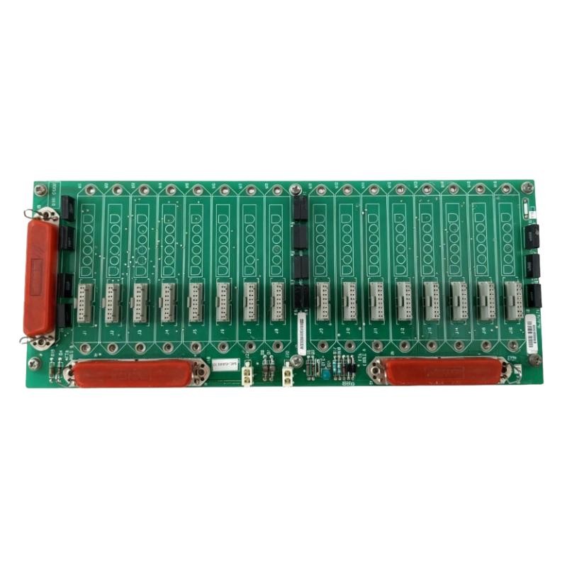
Before Installing the Honeywell 51304718-200
The first task is hardware identification.
Check the following items before removing the existing assembly:
Complete part number: 51304718-200
Module hardware revision
Associated I/O processor and system platform
Compatible HLAI/STI termination assembly
Connector condition and mechanical interface
Existing channel assignments
System configuration and firmware compatibility
The 51304718 series also includes related termination hardware. For example, the MU-GAIH83 and MC-GAIH83 configurations are associated with crimp-terminal HLAI/STI applications. Their compatibility must be checked against the actual installation.
Do not select an FTA based only on the shared 51304718 prefix.
Honeywell HLAI Module Installation Risks
Three installation issues deserve attention.
FTA mismatch
A termination assembly designed for a different signal or connection arrangement may prevent correct integration. Confirm the exact assembly designation before connecting field wiring.
Incorrect field wiring
Incorrect polarity, loose terminals, and damaged conductors can create misleading channel readings. Check the wiring drawings rather than relying on the previous installation's cable position.
Configuration mismatch
The control system must recognize the correct I/O hardware and channel arrangement. A physically installed module is not necessarily a correctly configured module.
Honeywell 51304718-200 Wiring and System Configuration
The wiring arrangement should follow the Honeywell-approved FTA documentation.
For each channel, verify:
Field instrument output type
Input channel assignment
Signal polarity
Cable shielding and grounding
Terminal identification
Transmitter power arrangement
Signal range and engineering scaling
For a conventional 4–20 mA process measurement, the expected relationship is:
| Input signal | Typical engineering scale |
|---|---|
| 4 mA | 0% |
| 8 mA | 25% |
| 12 mA | 50% |
| 16 mA | 75% |
| 20 mA | 100% |
These values illustrate standard linear scaling. The actual supported signal range and channel characteristics must be confirmed using the applicable Honeywell hardware documentation.
Where Smart Transmitter functionality is required, verify the complete HLAI/STI arrangement, including the termination hardware and supported transmitter communication functions.
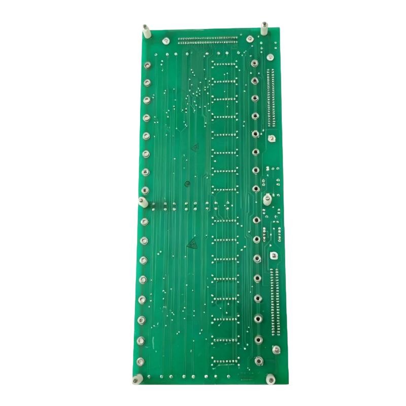
Commissioning the Honeywell 51304718-200 Analog Input
Commissioning should begin with a hardware status inspection.
Check that the module is properly seated and that the system diagnostic interface recognizes the installed I/O hardware.
Next, review the configured channel assignments and compare them with the plant I/O list.
A practical commissioning sequence is:
Hardware recognition
Confirm that the controller or I/O diagnostic interface identifies the expected module without hardware-related alarms.
Channel verification
Compare the configured channel numbers with the actual field wiring and termination drawings.
Signal injection
Where permitted, use an approved loop calibrator to apply known input signals. Confirm that the control system displays the corresponding values.
Engineering scaling
Check that the raw analog input is converted into the correct engineering units.
Field instrument verification
Reconnect the field transmitter and compare its process output with the value displayed by the operator station.
Commissioning Example: Pressure Transmitter Input Validation
Consider a representative commissioning scenario involving a pressure transmitter connected through a Honeywell HLAI/STI input arrangement.
The engineering display indicates 45% of the configured measurement range.
The technician applies a calibrated 12 mA reference signal using an approved test arrangement. For a standard 4–20 mA linear scale, this represents 50% of the measurement span.
If the display continues to show 45%, the engineer should investigate the input channel configuration and scaling before replacing the module.
The investigation should compare:
Calibrator output
Actual signal at the designated test point
Configured input channel
Raw controller input
Engineering-unit conversion
This is a representative commissioning example, not a documented Honeywell field-service case.
Honeywell 51304718-200 Installation Acceptance Criteria
Before handing the system back to operations, confirm that:
The installed part number matches the approved hardware list.
The associated FTA is compatible.
The module is mechanically secure.
All field connections match the wiring drawings.
Channel assignments are correct.
Analog readings match the calibration reference.
Engineering scaling is accurate.
No unexpected I/O diagnostic alarms remain.
Record the test results in the commissioning report. These measurements will provide a useful reference for subsequent maintenance and Fault Diagnosis.
Honeywell 51304718-200 Installation Long-Tail Keywords
Honeywell 51304718-200 installation guide
Honeywell 51304718-200 HLAI module setup
51304718-200 analog input commissioning
Honeywell high-level analog input wiring
Honeywell HLAI STI module installation
Honeywell 51304718-200 FTA compatibility
Honeywell analog input System Configuration
Honeywell Experion analog input troubleshooting
Frequently Asked Questions
What is the Honeywell 51304718-200 used for?
It is identified as a High-Level Analog Input / Smart Transmitter Interface-related component used in Honeywell process control installations.
What should be checked before installation?
Verify the hardware identification, associated FTA, terminal arrangement, I/O platform compatibility, and channel configuration.
Does the module support pressure and flow transmitters?
It is used in analog process measurement applications. Actual transmitter compatibility depends on the signal characteristics and complete system configuration.
Why is FTA compatibility important?
The FTA provides the field termination and electrical interface. An incorrect termination arrangement can prevent proper signal acquisition or system integration.
How can commissioning accuracy be verified?
Use an approved signal calibrator, compare the measured reference with the control-system input, and verify engineering scaling.
Conclusion
Reliable Honeywell 51304718-200 installation depends on correct HLAI/STI hardware identification, compatible termination assemblies, accurate wiring, and verified channel configuration. A measurement-based Setup and Commissioning process helps identify installation problems before the module is returned to normal process operation.