Honeywell 51304718-200 Analog Input Troubleshooting Guide (Channel Reading Fault Diagnosis)
Time:2026-11-03 Browse: 3
Honeywell 51304718-200 analog input reading errors can originate from the field transmitter, termination assembly, signal wiring, channel configuration, or I/O hardware. One common maintenance challenge is an incorrect process value even when the transmitter appears to be operating normally. Effective troubleshooting requires comparing the actual field signal with the value acquired by the Honeywell control system before deciding whether the HLAI module needs replacement.
A Typical Honeywell 51304718-200 Analog Input Failure
Consider a process measurement that gradually becomes lower than the actual field value.
The transmitter is operating, the process itself is stable, and no obvious cable damage is visible. However, the operator station displays a measurement that does not agree with the local instrument.
This type of fault should not immediately be classified as an internal module failure.
The engineer needs to establish where the discrepancy first appears.
The investigation should consider four separate values:
Actual process measurement.
Transmitter electrical output.
Signal received at the I/O termination.
Process value displayed by the controller.
Comparing these points helps distinguish instrumentation faults from input acquisition problems.
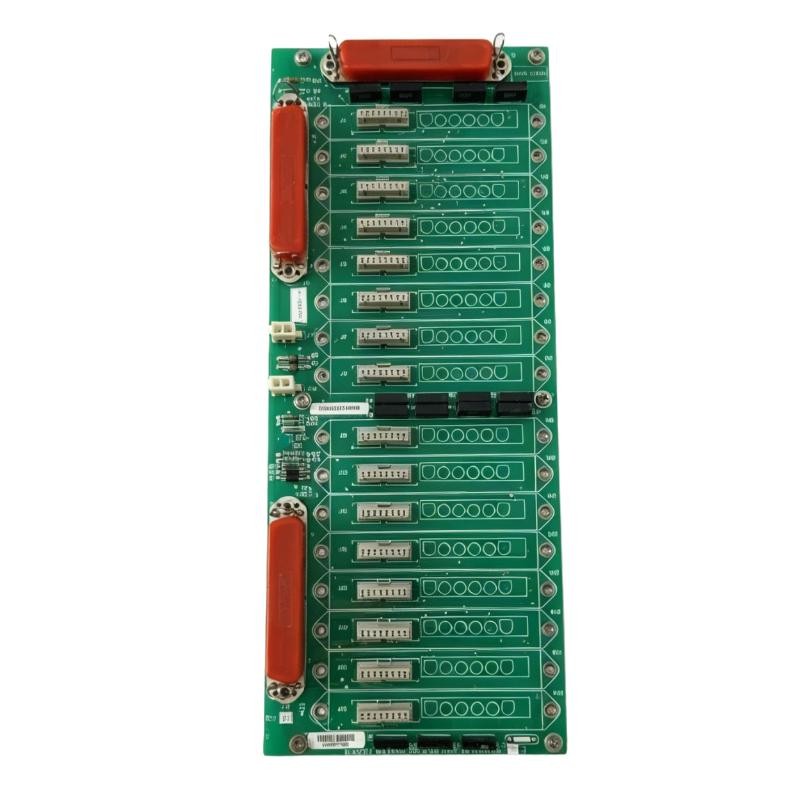

Fault Diagnosis: Why the Displayed Process Value Is Incorrect
A representative example involves a pressure transmitter configured for a 0–10 bar measurement range.
At an actual pressure of 5 bar, a correctly scaled 4–20 mA transmitter should produce approximately 12 mA.
Suppose the operator station displays only 4.5 bar.
The first diagnostic action is to measure the transmitter output using an approved loop-testing method.
If the transmitter produces 12 mA, but the controller continues to display 4.5 bar, attention should shift toward the signal path and configuration.
Possible causes include:
Incorrect channel scaling
Wrong channel assignment
Loose FTA termination
Incorrect wiring
Input configuration mismatch
Module or termination hardware problems
The important distinction is that the transmitter may be correct while the acquired engineering value is wrong.
Investigating the Honeywell 51304718-200 Signal Path
A useful diagnostic approach is to follow the signal from the field instrument toward the controller.
Field transmitter inspection
Verify the transmitter's configured range, output mode, and diagnostic status. Compare the local measurement with the electrical output.
FTA inspection
Check terminal tightness, connector condition, wiring identification, and the correct termination assembly.
I/O hardware inspection
Review the module status and available system diagnostics. Check whether the hardware is recognized correctly.
Controller configuration inspection
Compare the channel assignment and engineering scaling against the approved I/O database.
This sequence prevents technicians from repeatedly replacing field instruments when the actual fault is inside the control-system configuration.
Root Cause Investigation: Incorrect Input Scaling
One particularly important failure pattern is incorrect engineering scaling.
For example, a transmitter may operate over a 0–10 bar range, while the corresponding control-system channel is configured for a different range.
The electrical input may be perfectly stable, but the displayed process value will remain incorrect.
For a standard linear 4–20 mA measurement:
[
PV=\frac{I-4}{16}\times Span+LRV
]
Where:
PV = Process value
I = Measured current in mA
Span = Configured measurement span
LRV = Lower range value
At 12 mA, a transmitter configured for 0–10 bar should produce:
[
PV=\frac{12-4}{16}\times10=5\text{ bar}
]
If the control system displays another value, check the configured range and conversion settings.
These calculations are reference examples for conventional 4–20 mA scaling, not a claim about the specific internal conversion algorithm of the 51304718-200.
Honeywell 51304718-200 Troubleshooting: Intermittent Input Fluctuations
Another fault pattern occurs when the analog input value changes unexpectedly even though the process is stable.
The engineer should investigate the following conditions.
Loose termination connections
Vibration, cabinet maintenance, and aging terminal hardware can create intermittent electrical connections.
Inspect the field wiring and associated FTA connections.
Electromagnetic interference
Signal cables routed alongside motor feeders, variable-frequency drives, or high-current conductors may experience interference.
Check cable separation, shielding, and grounding practices.
Unstable transmitter output
A fluctuating measurement at the transmitter terminals indicates that the problem may be outside the I/O module.
Check transmitter power, sensor condition, and process connections.
Hardware or connector problems
If the field signal is stable but the acquired value fluctuates, inspect the module seating, connector condition, and available I/O diagnostics.
Do not remove or reseat energized hardware unless the approved Honeywell system procedure permits it.
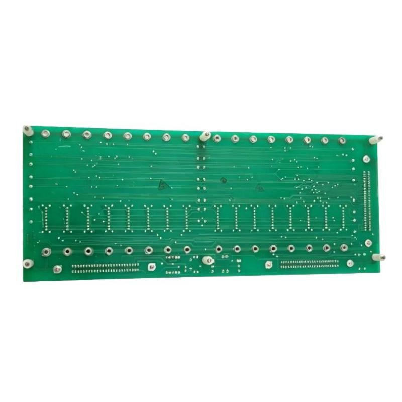
A Different Failure Scenario: Smart Transmitter Communication Problems
The 51304718 family is associated with HLAI/STI termination configurations.
Where Smart Transmitter functionality is used, a communication problem may occur even when the basic analog measurement remains available.
For this condition, separate the analog measurement path from the digital communication path during diagnosis.
Check:
Whether the analog process value is still updating.
Whether the transmitter is correctly identified by the engineering tools.
Whether the configured FTA matches the installed hardware.
Whether the transmitter communication wiring is correct.
Whether the relevant system diagnostics report a communication problem.
A normal analog reading does not necessarily prove that every Smart Transmitter communication function is operating correctly.
Similarly, loss of digital communication does not automatically establish that the analog input circuitry has failed.
Repair Strategy for Honeywell 51304718-200
The repair should address the confirmed fault rather than the most obvious component.
| Confirmed problem | Recommended corrective action |
|---|---|
| Incorrect scaling | Correct channel engineering configuration |
| Loose field connection | Repair and secure the termination |
| Damaged cable | Replace the affected conductor |
| Incorrect FTA | Install the approved compatible assembly |
| Unstable transmitter | Inspect transmitter power and instrumentation |
| Module diagnostic fault | Investigate hardware status and perform approved replacement testing |
| STI communication fault | Verify compatible termination and communication configuration |
When module replacement is necessary, verify the complete part number and hardware compatibility.
The 51304718 family includes different termination configurations, such as compression and crimp-terminal variants. These should not be treated as interchangeable solely because their part numbers share the same prefix.
Post-Repair Verification and System Recovery
After corrective work, repeat the original measurements.
For the 0–10 bar example, the following reference points can be used:
| Pressure | Expected current |
|---|---|
| 0 bar | 4 mA |
| 2.5 bar | 8 mA |
| 5 bar | 12 mA |
| 7.5 bar | 16 mA |
| 10 bar | 20 mA |
Confirm that the control system displays the correct engineering value at each test point.
After the test:
Restore the original field wiring.
Remove any temporary test connections.
Verify channel status.
Check for active system alarms.
Confirm that the process value updates normally.
Record the final measurements and repair details.
For intermittent problems, monitor the input under normal operating conditions rather than relying exclusively on a short calibration test.
Honeywell 51304718-200 Troubleshooting Long-Tail Keywords
Honeywell 51304718-200 troubleshooting guide
Honeywell 51304718-200 analog input fault
Honeywell HLAI module incorrect reading
51304718-200 channel diagnostic problems
Honeywell high-level analog input signal failure
Honeywell HLAI STI communication troubleshooting
Honeywell 51304718-200 repair procedure
Honeywell analog input scaling error
Honeywell FTA wiring fault diagnosis
Honeywell Experion analog input channel failure
Frequently Asked Questions About Honeywell 51304718-200 Faults
Why does the Honeywell analog input display an incorrect value?
Possible causes include incorrect scaling, transmitter output problems, wiring errors, termination faults, and hardware configuration mismatches.
Can a faulty FTA cause an incorrect analog reading?
Yes. Loose connections, damaged terminals, or an incompatible termination assembly can affect the signal reaching the I/O hardware.
What should be checked before replacing the module?
Verify the transmitter output, wiring, FTA compatibility, channel configuration, and system diagnostics.
Why does the analog value fluctuate when the process is stable?
Investigate electrical interference, grounding, loose connections, transmitter instability, and module connector condition.
Does an STI communication fault always mean analog input failure?
No. The analog measurement and smart-transmitter communication functions should be evaluated separately.
Can another 51304718-series component replace the 51304718-200?
Not automatically. Verify the exact component function, termination arrangement, hardware revision, and Honeywell system compatibility.
Engineering Conclusion
Honeywell 51304718-200 troubleshooting should focus on locating the first point where the measured signal differs from the expected value.
In practical process automation maintenance, an incorrect analog reading is not sufficient evidence of an internal I/O module failure. A structured comparison of transmitter output, FTA termination, hardware diagnostics, and controller scaling provides a more reliable Fault Diagnosis.
This measurement-driven approach reduces unnecessary hardware replacement and helps restore accurate process monitoring with minimal disruption to the control system.