Schneider NT10H1 1000A Circuit Breaker Installation Guide and Commissioning
Time:2026-11-04 Browse: 1
Schneider NT10H1 Circuit Breaker Installation Overview
The Schneider MasterPact NT10H1 1000A circuit breaker requires careful verification of its frame configuration, trip unit compatibility, electrical connections, and protection settings before commissioning. Incorrect installation or an unsuitable protection configuration can lead to nuisance tripping, overheating, or inadequate short-circuit protection.
The NT10H1 belongs to the MasterPact NT range and is designed for low-voltage power distribution systems. Its H1 performance classification provides a rated ultimate short-circuit breaking capacity (Icu) of 42 kA at 440 V AC. The rated operational voltage reaches 690 V AC at 50/60 Hz.
An important detail during an NT10H1 Installation Guide review is that the model designation alone does not identify every mechanical configuration. Schneider offers fixed and drawout versions, as well as three-pole and four-pole arrangements. The corresponding catalog references must be checked before preparing the switchboard.
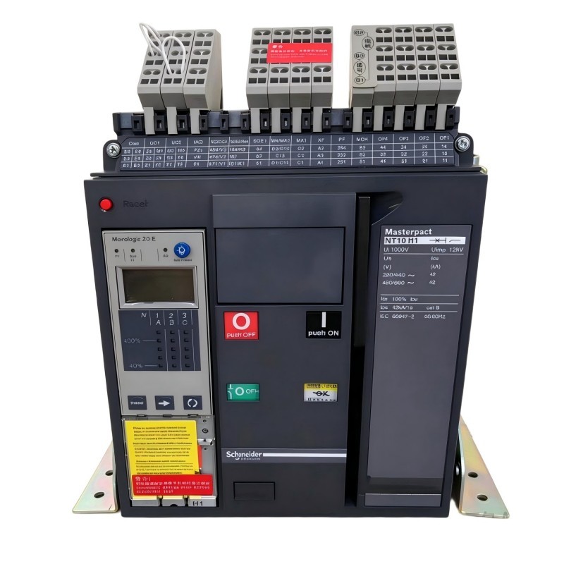
Schneider NT10H1 Technical Characteristics and Selection
The following characteristics are relevant when planning the installation and System Configuration:
| Parameter | Specification |
|---|---|
| Product range | MasterPact NT |
| Model | NT10H1 |
| Product type | Air circuit breaker |
| Rated current | 1000 A at 40°C |
| Poles | 3P or 4P, depending on version |
| Rated operational voltage | Up to 690 V AC |
| Frequency | 50/60 Hz |
| Breaking capacity | 42 kA at 440 V AC |
| Insulation voltage (Ui) | 1000 V AC |
| Impulse withstand voltage (Uimp) | 12 kV |
| Maximum breaking time | 25 ms |
| Standard | IEC 60947-2 |
The 1000 A frame rating should not automatically be treated as the configured protection pickup current. The sensor rating and trip-unit arrangement must be verified separately.
For example, Schneider catalog reference 47130 identifies a fixed, three-pole NT10H1 frame supplied without a trip unit. Reference 47220 identifies a drawout, three-pole version with the same basic frame rating.
Installation Preparation for the Schneider NT10H1
Before positioning the circuit breaker, inspect the switchboard drawings and confirm that the available installation space matches the selected version.
The preparation work should cover:
Verify the complete Schneider reference number and nameplate information.
Confirm whether the breaker is fixed-mounted or drawout-mounted.
Check the number of poles and neutral arrangement.
Verify the rated current and sensor compatibility.
Confirm the required trip unit and protection functions.
Review the busbar current rating and short-circuit withstand capability.
Check the manufacturer's mounting, clearance, and connection requirements.
The electrical system must be isolated before installation. Apply the site's lockout/tagout procedure, verify the absence of voltage with an appropriately rated tester, and discharge stored energy where applicable.
A 1000 A circuit breaker is not a component for trial-and-error installation. Mechanical alignment, connection quality, and protection coordination must be checked by qualified electrical personnel.
Schneider NT10H1 Mechanical Mounting and Busbar Connections
The mechanical installation method depends on the selected NT10H1 configuration.
For a fixed-mounted breaker, inspect the mounting supports and verify that the frame is securely positioned. The busbar connection surfaces must be clean, undamaged, and free from contamination.
For a drawout version, inspect the chassis, guide rails, racking mechanism, and position indicators. The breaker must move correctly between the disconnected, test, and connected positions according to the applicable Schneider instructions.
Particular attention should be given to the following areas:
Busbar alignment: Misaligned busbars can introduce mechanical stress into the terminal connections. Do not force the breaker into position to compensate for incorrect alignment.
Contact surfaces: Check for oxidation, scratches, deformation, or foreign material.
Connection torque: Apply the specified torque from the installation documentation for the exact connection hardware. Do not substitute a generic torque value based only on the frame rating.
Phase identification: Confirm phase sequence and terminal identification against the switchboard drawings.
The NT10H1 is a power circuit breaker, not a PLC Controller or signal-processing Module. Its commissioning therefore focuses on primary power connections, mechanical operation, protection configuration, and auxiliary circuit integration.
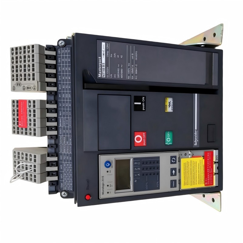
NT10H1 Protection Setup and System Configuration
Protection configuration is one of the most important parts of Schneider NT10H1 Setup and Commissioning.
The frame rating of 1000 A does not establish the actual long-time, short-time, instantaneous, or ground-fault settings. These depend on the installed trip unit, sensor rating, system design, and coordination study.
Before energization, engineers should verify:
Long-time protection settings against the protected cable and equipment ratings.
Short-time protection and coordination with downstream devices.
Instantaneous protection where applicable.
Ground-fault protection where the installed trip unit supports it.
Compatibility between the trip unit, sensor, and breaker frame.
Auxiliary contact and remote indication wiring.
Electrical and mechanical interlocking requirements.
For installations connected to a PLC-based monitoring system, auxiliary contacts may provide breaker status information. The PLC input configuration should distinguish between open, closed, tripped, and unavailable states where the available contacts permit this.
Never assume that the NT10H1 includes a particular communication interface or trip unit simply because the breaker frame carries the H1 designation.
Schneider NT10H1 Commissioning and Functional Validation
A proper commissioning procedure should verify both mechanical performance and electrical protection.
Before energization, inspect all accessible connections and confirm that the switchboard is free from tools, loose hardware, and foreign objects.
The commissioning checks should include:
Verify the mechanical ON/OFF mechanism and spring-charging operation.
Check the drawout position indicators if applicable.
Confirm that interlocks operate according to the manufacturer's requirements.
Verify auxiliary contacts and remote status indications.
Perform the prescribed trip-unit self-tests and secondary injection tests where applicable.
Complete primary injection testing when required by the commissioning specification.
Confirm that protection settings match the approved coordination study.
Record test results and equipment identification.
A secondary injection test checks the response of the electronic protection unit without reproducing the full primary current path. Primary injection testing provides a more comprehensive assessment of the installed current-sensing and protection chain.
Testing methods and acceptance limits must follow the applicable Schneider documentation and project specifications.
Field Engineering Example: NT10H1 Commissioning Verification
Consider a representative commissioning scenario involving a 1000 A NT10H1 installed in a low-voltage distribution panel.
During the initial inspection, the engineering team finds that the mechanical frame is correctly positioned, but the protection documentation does not match the installed trip-unit configuration.
Rather than energizing the breaker immediately, the team compares the equipment nameplate, catalog reference, sensor rating, and approved protection study.
The discrepancy is resolved by confirming the installed protection hardware and updating the commissioning records before functional testing.
This example illustrates an important field practice: a correctly installed circuit breaker frame does not automatically mean that the complete protection system is correctly configured.
Schneider NT10H1 Installation and Commissioning Checklist
| Inspection item | Expected result |
|---|---|
| Model identification | NT10H1 confirmed |
| Mounting arrangement | Matches drawings |
| Pole configuration | Correct |
| Busbar connections | Aligned and secured |
| Connection torque | Meets manufacturer specification |
| Trip unit | Correct and compatible |
| Protection settings | Match coordination study |
| Auxiliary circuits | Correct operation |
| Mechanical interlocks | Functional |
| Electrical testing | Accepted |
| Commissioning records | Completed |
Long-Tail Keywords for Schneider NT10H1 Installation
This guide also addresses the following technical search topics:
Schneider NT10H1 1000A circuit breaker installation guide
MasterPact NT10H1 setup and commissioning procedure
Schneider NT10H1 fixed and drawout circuit breaker installation
NT10H1 busbar connection inspection
Schneider MasterPact NT10H1 protection configuration
NT10H1 circuit breaker functional testing
Schneider NT10H1 42kA short-circuit rating
MasterPact NT10H1 electrical commissioning checklist
Correct product identification, mechanical installation, protection coordination, and documented testing form the foundation of a reliable NT10H1 installation.