Schneider NT10H1 Circuit Breaker Troubleshooting: Failure to Close and Control Diagnosis
Time:2026-11-04 Browse: 1
Why the Schneider NT10H1 Circuit Breaker May Fail to Close
When a Schneider MasterPact NT10H1 circuit breaker refuses to close, the problem is not necessarily caused by a defective breaker mechanism. In practical maintenance work, the first areas to investigate are the spring-charging mechanism, electrical closing circuit, undervoltage release, safety interlocks, and drawout position.
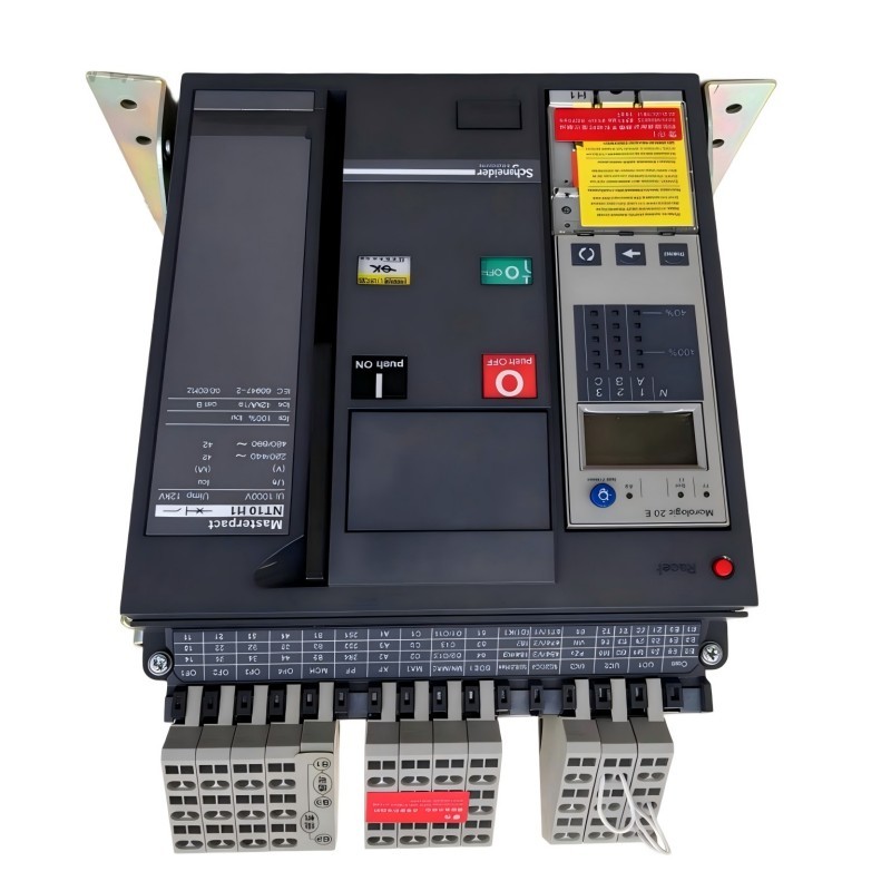
The Schneider NT10H1 is a 1000 A MasterPact NT air circuit breaker with an H1 short-circuit performance rating of 42 kA at 440 V AC. It is used in power distribution applications where reliable switching and protection are essential.
A failure-to-close condition can interrupt power restoration even when the incoming supply and downstream equipment are operating normally. Effective NT10H1 Troubleshooting therefore requires separating mechanical restrictions from electrical control faults before considering component replacement.
Schneider NT10H1 Failure Symptoms and Initial Observations
A maintenance engineer should first establish exactly what happens when a closing command is issued.
Typical symptoms include:
The closing push-button does not operate the breaker.
The spring-charging indicator shows that the mechanism is not ready.
The breaker remains open despite a valid electrical closing command.
The drawout mechanism cannot reach the connected position.
The breaker closes mechanically but immediately opens again.
The remote PLC system indicates an incorrect breaker status.
The closing mechanism operates intermittently.
These symptoms do not point to one universal failure. For example, a breaker that cannot close because its spring is not charged requires a different Fault Diagnosis process from a breaker that receives a closing command but remains mechanically blocked.
The first diagnostic question should be: Is the closing mechanism unavailable, or is an electrical interlock preventing the closing operation?
NT10H1 Troubleshooting: Understanding the Closing Mechanism
The MasterPact NT10H1 uses a stored-energy operating mechanism. Depending on the selected configuration, spring charging and closing can involve manual operation, electrical accessories, or both.
If the breaker cannot close, inspect the mechanical operating indicators before testing the control circuit.
Check the following conditions:
Stored-energy mechanism: Confirm whether the closing spring is charged. An uncharged spring can prevent the breaker from completing its closing operation.
Mechanical position: Verify that the breaker is in an allowed operating position. Drawout models require correct chassis positioning and engagement.
Interlocks: Inspect mechanical and electrical interlocks. Door interlocks, racking interlocks, and other safety devices may intentionally prevent closing.
Trip-free condition: Confirm whether a protection trip or an active opening command is preventing the mechanism from remaining closed.
Do not bypass an interlock to restore operation. Identify the reason for the blocking condition and correct it according to the manufacturer's instructions.
Schneider NT10H1 Electrical Closing Circuit Fault Diagnosis
When the mechanical mechanism appears ready, the next stage is electrical Troubleshooting.
The closing circuit may include a closing release, auxiliary contacts, undervoltage release, control fuses, terminal connections, and external interlocking devices.
The actual accessory arrangement must be confirmed from the breaker documentation.
A useful diagnostic sequence is:
| Inspection point | Possible fault | Diagnostic action |
|---|---|---|
| Control power supply | Missing voltage | Measure against accessory nameplate |
| Closing release | Coil open circuit or damage | Inspect and test according to manufacturer procedure |
| Control fuse | Open fuse | Check continuity after isolation |
| Auxiliary contacts | Incorrect contact state | Verify contact operation |
| Undervoltage release | Insufficient supply | Check specified operating voltage |
| Interlock circuit | Active blocking condition | Trace the control circuit |
| Terminal connections | Loose or damaged wiring | Inspect and verify connections |
One important field observation is that a control voltage reading should always be interpreted against the actual accessory rating.
For example, a closing release designed for a particular AC or DC control voltage cannot be evaluated using an assumed universal voltage value.
If the measured supply is outside the accessory's specified operating range, investigate the control transformer, power supply, wiring, and fuse protection before replacing the release.
Representative NT10H1 Fault Investigation: Breaker Does Not Respond to Remote Closing
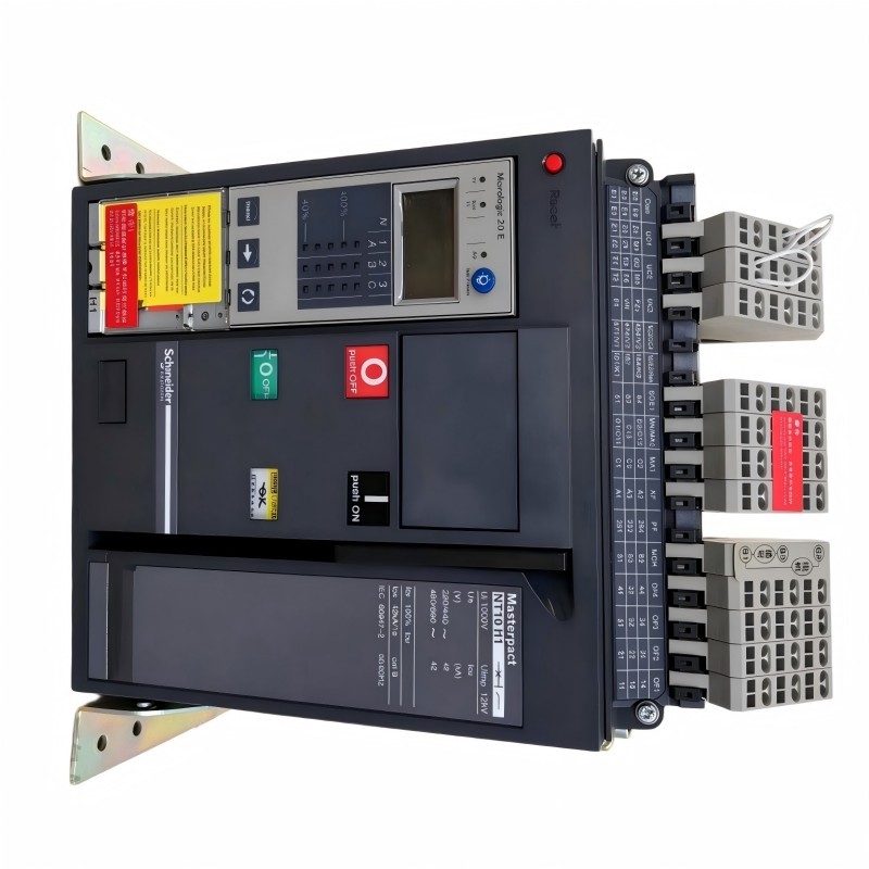
Consider a representative maintenance scenario in which a Schneider NT10H1 operates normally from the local control mechanism but fails to respond to a remote closing command.
The PLC system displays the breaker as open, and the remote command is recorded as active. However, the breaker does not close.
The diagnostic process begins by separating the PLC command from the actual breaker operating circuit.
Initial observation
The local mechanical mechanism appears operational, but the remote closing function is unavailable.
Signal investigation
The engineer checks the PLC output status, intermediate relay, control fuse, and closing circuit wiring.
A hypothetical test result shows:
PLC output command: ON
Intermediate relay output: ON
Closing-release supply: 0 V during the closing request
The 0 V measurement is an illustrative diagnostic result, not a published NT10H1 specification.
Root cause investigation
The missing voltage indicates that the problem is downstream of the PLC output. The engineer traces the control wiring and discovers an open contact in the external interlocking circuit.
Corrective action
After confirming that the interlock condition is no longer required and that all safety conditions are satisfied, the faulty contact is repaired or replaced. The closing circuit is then tested again.
Verification
The remote command is repeated, and the breaker operating response and auxiliary status feedback are checked.
This type of investigation demonstrates why replacing the circuit breaker immediately is often an inefficient troubleshooting decision. The actual failure may be located in the external control system rather than inside the breaker.
NT10H1 Drawout Mechanism and Position-Related Faults
Another failure pattern involves the drawout version of the Schneider NT10H1.
If the breaker cannot be moved into the connected position, inspect the chassis and racking mechanism before investigating the electronic protection system.
Potential causes include:
Incorrect alignment between the breaker and chassis.
Foreign objects or mechanical obstruction.
Damaged or contaminated guide surfaces.
Racking mechanism wear.
Incorrect position indication.
An active mechanical interlock.
Incomplete engagement of the drawout assembly.
The drawout version must be operated according to the manufacturer's prescribed procedure.
Never force the racking handle when resistance is encountered. Excessive force can damage mechanical components and create additional problems during subsequent commissioning.
Position indicators should also be checked against the actual mechanical position. A disagreement between the indicator and physical position can affect operating permissions and remote monitoring.
Schneider NT10H1 Unexpected Tripping: Protection-Related Diagnosis
If the NT10H1 closes successfully but subsequently trips, the investigation should shift from the closing mechanism to the protection system.
Possible causes include:
Overload current exceeding the configured long-time protection threshold.
Short-circuit current exceeding the applicable protection setting.
Ground-fault conditions, if the installed trip unit supports this function.
Incorrect protection coordination.
Defective or incompatible sensing components.
A genuine downstream electrical fault.
The 1000 A frame rating must not be confused with the actual protection pickup setting.
For example, a 1000 A NT10H1 frame may be configured with a lower sensor rating. Therefore, the engineer must verify the installed sensor and trip-unit configuration before interpreting current measurements.
A practical Fault Diagnosis comparison should include:
| Measurement | Engineering purpose |
|---|---|
| Phase A current | Identify abnormal loading |
| Phase B current | Compare phase loading |
| Phase C current | Detect phase imbalance |
| Neutral current | Investigate neutral loading where applicable |
| Trip indication | Identify the protection function involved |
| Event history | Establish the sequence of operation |
If a trip occurs immediately after energization, investigate the actual electrical fault before attempting another closing operation.
Repeatedly resetting and reclosing a breaker without identifying the cause can expose equipment and personnel to serious hazards.
Schneider MasterPact NT10H1 Repair and Maintenance Considerations
Repair decisions should be based on the identified fault rather than the visible symptom alone.
For a control-circuit problem, inspect the relevant wiring, connectors, auxiliary contacts, and electrical accessories.
For a mechanical problem, inspect the operating mechanism, spring-charging components, and drawout chassis where applicable.
For a protection-related issue, verify the trip unit, sensing arrangement, protection settings, and recorded trip information.
The NT10H1 designation covers different product configurations. Some catalog references identify a breaker frame supplied without a trip unit. Consequently, the presence of a protection function or a particular electronic accessory must never be assumed.
If internal damage, abnormal mechanical resistance, contact deterioration, or insulation damage is found, remove the breaker from service and arrange inspection by an authorized or appropriately qualified service provider.
NT10H1 Troubleshooting: Post-Repair Functional Verification
After corrective maintenance, the breaker should undergo a structured verification process.
The following checks help establish whether the original fault has been resolved:
Confirm the breaker model and accessory configuration.
Inspect repaired control-circuit connections.
Verify the closing and opening mechanisms.
Check spring-charging operation.
Test auxiliary contacts and remote status feedback.
Verify electrical interlocks.
Check drawout position indication where applicable.
Perform the required trip-unit and protection tests.
Record the final test results.
Where the breaker has undergone internal repair or significant mechanical maintenance, follow Schneider's applicable inspection and testing requirements before returning it to service.
The repair record should include the original symptom, diagnostic measurements, identified root cause, replaced components, and final functional test results.
Long-Tail Keywords for Schneider NT10H1 Troubleshooting
This fault investigation covers several specific maintenance-related search topics:
Schneider NT10H1 circuit breaker troubleshooting guide
MasterPact NT10H1 breaker fails to close
Schneider NT10H1 remote closing fault diagnosis
NT10H1 spring charging mechanism problems
Schneider MasterPact NT10H1 undervoltage release troubleshooting
NT10H1 drawout circuit breaker position fault
Schneider NT10H1 unexpected tripping diagnosis
MasterPact NT10H1 electrical control circuit repair
Schneider NT10H1 auxiliary contact fault
NT10H1 1000A circuit breaker maintenance procedure
Final Engineering Assessment of Schneider NT10H1 Faults
A Schneider NT10H1 failure should be investigated through the complete operating chain, including the breaker mechanism, electrical accessories, external interlocks, protection configuration, and switchboard control system.
The most effective troubleshooting approach is to identify where the operating sequence stops, verify the relevant electrical or mechanical condition, and confirm the result after corrective maintenance.
This method reduces unnecessary component replacement and helps maintain reliable operation of MasterPact NT power distribution equipment.