Schneider NT12H1 1250A Air Circuit Breaker Installation and Commissioning Guide
Time:2026-11-04 Browse: 1
Schneider NT12H1 Installation Guide: Product Overview
The Schneider MasterPact NT12H1 1250A air circuit breaker requires correct frame selection, busbar preparation, protection-system configuration, and mechanical verification before commissioning. Its H1 breaking-capacity classification provides a rated ultimate short-circuit breaking capacity (Icu) of 42 kA, including at 440 V AC.
The NT12H1 is part of Schneider Electric's MasterPact NT low-voltage circuit breaker family. It is designed for power distribution protection in industrial switchboards, main distribution boards, and other high-current electrical installations.
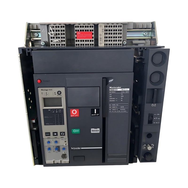
One important installation consideration is that NT12H1 identifies the breaker frame and performance class, not necessarily the complete supplied configuration. Fixed and drawout versions, three-pole and four-pole arrangements, and different trip-unit combinations must be distinguished before installation.
Schneider NT12H1 Technical Specifications for Installation Planning
The following parameters provide a reference for engineering selection and System Configuration.
| Parameter | Technical specification |
|---|---|
| Manufacturer | Schneider Electric |
| Product family | MasterPact NT |
| Model | NT12H1 |
| Product type | Air circuit breaker |
| Rated frame current | 1250 A |
| Rated current reference temperature | 40°C |
| Breaking-capacity class | H1 |
| Ultimate breaking capacity (Icu) | 42 kA |
| Icu reference voltage | 440 V AC |
| Rated operational voltage | Up to 690 V AC |
| Frequency | 50/60 Hz |
| Rated insulation voltage (Ui) | 1000 V AC |
| Impulse withstand voltage (Uimp) | 12 kV |
| Rated short-time withstand current (Icw) | 42 kA for 1 s |
| Rated short-circuit making capacity (Icm) | 88 kA |
| Applicable standard | IEC 60947-2 |
The actual supplied equipment must be checked against its complete catalog reference.
For example:
47140: NT12H1, 1250 A, three-pole, fixed, without control unit.
47145: NT12H1, 1250 A, four-pole, fixed, without control unit.
47230: NT12H1, 1250 A, three-pole, drawout, without control unit.
These distinctions are important because the mounting arrangement and neutral configuration affect switchboard preparation.
Engineering Considerations Before Schneider NT12H1 Installation
Before installing an NT12H1, the engineering team should establish whether the breaker is intended for a new switchboard or replacement of an existing unit.
For a new installation, the main concern is compatibility between the circuit breaker and the electrical distribution design.
For a replacement project, the existing chassis, busbar arrangement, control wiring, and accessory configuration require additional inspection.
The preparation review should cover:
Rated operating voltage and system frequency.
Maximum prospective short-circuit current.
Required breaking capacity.
Three-phase and neutral configuration.
Busbar current-carrying capacity.
Protection coordination with upstream and downstream breakers.
Trip-unit and current-sensor compatibility.
Fixed or drawout mounting requirements.
Auxiliary control and indication circuits.
The 1250 A frame rating does not automatically establish the protection pickup current. The installed sensor and trip unit determine the available protection configuration.
A breaker supplied without a control unit must not be treated as a complete protection assembly until the required compatible control unit has been selected and installed.
Schneider NT12H1 Mechanical Installation and Mounting Inspection
The mounting procedure depends on whether the NT12H1 is fixed or drawout.
For a fixed version, the mounting structure must provide adequate mechanical support. Check the installation dimensions, terminal orientation, and busbar alignment against the relevant Schneider drawings.
For a drawout version, the chassis and racking assembly must be inspected before inserting the breaker. Guide rails, position indicators, mechanical interlocks, and racking components should operate without abnormal resistance.
Particular attention is required in high-current switchboards because mechanical misalignment can create additional stress on primary electrical connections.
The following inspection areas deserve attention:
Mounting structure: Verify that the support structure is suitable for the breaker weight and operating forces.
Primary terminals: Inspect for surface damage, contamination, oxidation, and deformation.
Busbar positioning: Confirm that the connection arrangement matches the manufacturer's drawings.
Mechanical interlocks: Verify that the breaker cannot enter an unauthorized operating position.
Clearance: Maintain the required electrical clearances and ventilation spaces specified for the selected assembly.
All installation work must be performed with the electrical system isolated, locked out, and verified de-energized by qualified personnel.
NT12H1 Primary Connection and Electrical Wiring Requirements
The primary power connections are a critical part of Schneider NT12H1 Installation Guide procedures.
Poor contact conditions can cause localized heating, insulation deterioration, and eventual equipment failure.
During installation, engineers should:
Inspect all primary connection surfaces.
Confirm the correct phase arrangement.
Verify that busbar dimensions and current ratings are suitable.
Check the connection hardware against the manufacturer's assembly documentation.
Apply the specified tightening torque.
Inspect the completed connections before closing the switchboard.
Do not apply a generic torque value based only on the 1250 A rating. The required torque depends on the actual terminal hardware and connection arrangement.
Auxiliary wiring must be treated separately from the main power circuit.
Depending on the selected accessories, the control circuit may include opening releases, closing releases, undervoltage releases, auxiliary contacts, and remote status signals.
Where the NT12H1 is integrated into a PLC-based monitoring system, the auxiliary contacts can be used to provide breaker status information.
The PLC Controller should distinguish between breaker open, breaker closed, and trip indications according to the available contact arrangement. Signal polarity and contact logic must be verified during testing.
Schneider NT12H1 Protection Setup and System Configuration
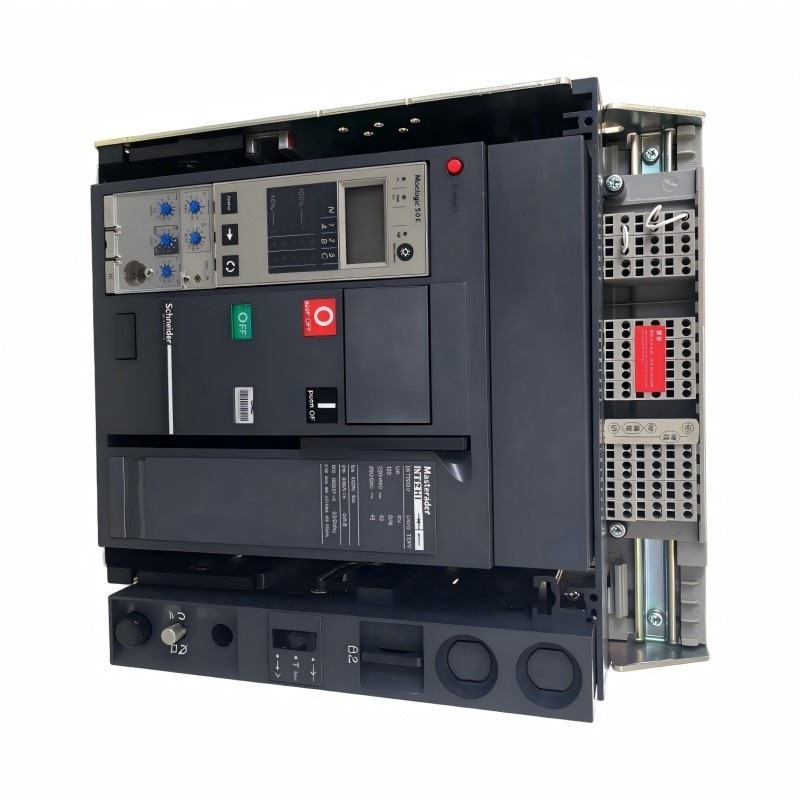
Protection configuration must be completed before the breaker is placed into normal service.
The NT12H1 H1 designation describes the short-circuit performance class. It does not identify the complete electronic protection configuration.
The engineering team should verify:
Installed MicroLogic trip-unit model.
Current-sensor rating.
Long-time pickup and delay.
Short-time pickup and delay.
Instantaneous protection.
Ground-fault protection, if supported.
Coordination with downstream protective devices.
Compatibility with the switchboard's grounding arrangement.
The NT12H1 product family supports different sensor ratings, including 630 A, 800 A, 1000 A, and 1250 A in the documented configurations.
The protection settings must be established from the approved electrical study rather than selected simply because the frame is rated at 1250 A.
For systems with multiple distribution levels, engineers should also check selectivity and backup protection requirements.
Schneider NT12H1 Commissioning and Functional Testing
The NT12H1 Setup and Commissioning process should establish that the breaker operates correctly both mechanically and electrically.
Before energization, confirm that all installation checks have been completed and that the protection configuration has been approved.
The commissioning work should include:
Mechanical operation: Verify opening, closing, spring charging, and position indication.
Electrical accessories: Check the operating response of installed releases and auxiliary contacts.
Interlocking: Verify mechanical and electrical interlocks.
Protection testing: Perform the required trip-unit verification and secondary injection testing.
Primary circuit verification: Conduct primary injection testing where required by the project specification.
Monitoring integration: Verify that remote indications and PLC input signals correspond to actual breaker states.
Secondary injection testing evaluates the protection unit's response to injected test signals. Primary injection testing provides a broader check of the installed current-sensing and protection chain.
Testing procedures and acceptance limits must follow the applicable Schneider instructions and commissioning specifications.
NT12H1 Commissioning Example: Current Sensor and Trip Unit Verification
Consider a representative commissioning scenario involving an NT12H1 installed in a 1250 A main distribution board.
During document review, the commissioning engineer identifies a difference between the current-sensor rating listed in the electrical drawings and the sensor installed in the breaker.
Instead of proceeding directly to energization, the engineer checks the breaker nameplate, sensor identification, trip-unit model, and approved protection coordination study.
The investigation establishes that the breaker frame is correctly rated, but the documentation must be reconciled with the actual protection hardware.
The team then verifies the protection settings and completes the required injection tests before releasing the equipment for service.
This example illustrates an important field principle: a correct breaker frame rating does not prove that the complete protection assembly is correctly configured.
Schneider NT12H1 Installation Quality Checklist
| Inspection item | Acceptance requirement |
|---|---|
| Model identification | NT12H1 confirmed |
| Frame rating | 1250 A |
| Pole configuration | Matches drawings |
| Mounting type | Fixed or drawout verified |
| Busbar arrangement | Compatible |
| Primary connections | Correctly assembled |
| Tightening torque | Manufacturer specification |
| Trip unit | Compatible and verified |
| Sensor rating | Confirmed |
| Protection settings | Approved study |
| Auxiliary wiring | Functionally checked |
| Mechanical operation | Normal |
| Electrical testing | Completed |
| Commissioning records | Approved |
Long-Tail Keywords for Schneider NT12H1 Installation and Setup
Schneider NT12H1 1250A air circuit breaker installation guide
Schneider MasterPact NT12H1 setup and commissioning
NT12H1 fixed circuit breaker installation procedure
NT12H1 drawout air circuit breaker mounting guide
Schneider NT12H1 42kA breaking capacity
MasterPact NT12H1 busbar connection requirements
Schneider NT12H1 MicroLogic trip unit configuration
NT12H1 current sensor selection
Schneider NT12H1 protection coordination and testing
MasterPact NT12H1 electrical commissioning checklist
A reliable Schneider NT12H1 installation depends on correct frame selection, compatible protection hardware, sound primary connections, and documented functional testing. These checks provide a practical foundation for commissioning a 1250 A low-voltage distribution breaker.