ABB 1MRK000173-BEr01 Binary I/O Module Installation Guide (Wiring & Commissioning)
Time:2026-05-26 Browse: 27
ABB 1MRK000173-BEr01 installation issues are most often not related to the module itself, but to incorrect RL110 voltage wiring, improper grounding, or mismatch in relay logic configuration inside ABB protection systems such as REx670. In several commissioning cases, the module appeared “faulty” while the real problem was incorrect field wiring polarity on digital inputs.
This module integrates 8 digital inputs and 10+2 outputs, designed for high-density binary signal handling in protection and automation environments.
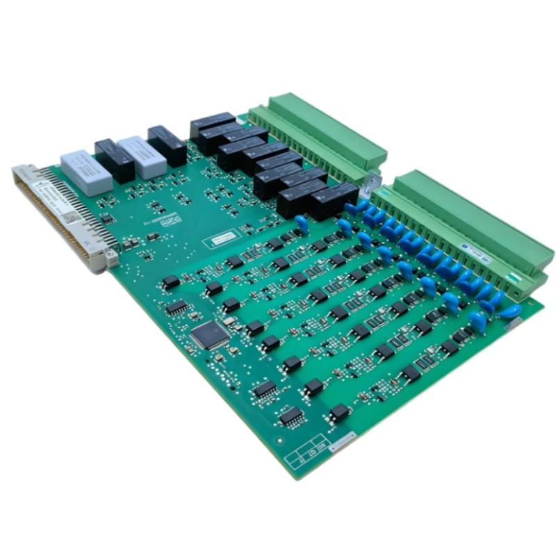
<h2>ABB 1MRK000173-BEr01 PLC Module Installation Overview</h2>
The ABB 1MRK000173-BEr01 Binary I/O Module is commonly used in substation automation systems and relay-based control architectures. It acts as a signal interface between field devices and ABB protection relays, especially in systems requiring fast switching (<10 ms response).
In one field installation at a power distribution station, the module was used to connect breaker status signals and trip circuits. Engineers initially underestimated the importance of correct voltage matching (110–125 VDC RL110 range), which later caused intermittent input recognition.
<h2>ABB 1MRK000173-BEr01 Wiring Preparation & Power Verification</h2>
Before installation, verify:
Input supply: 110–125 VDC (RL110 system)
Output configuration: relay + transistor mixed output structure
Cabinet grounding resistance: < 1Ω recommended
Terminal tightness: vibration-rated torque required
A common mistake observed in commissioning:
Field technicians connected 110 VDC inputs without checking common reference grounding. As a result, input channels showed unstable ON/OFF flickering.
After correcting the grounding reference, signal stability improved immediately.
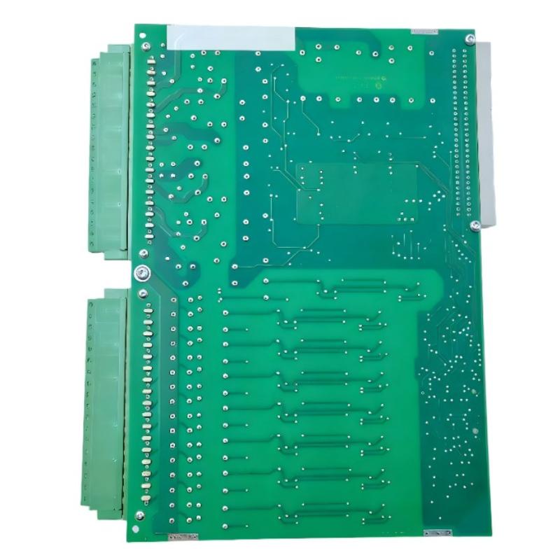
<h2>ABB 1MRK000173-BEr01 Commissioning & Signal Validation</h2>
During commissioning, the correct procedure is not just powering the module but validating signal integrity under load conditions.
In one case study:
Input signals from breaker auxiliary contacts were tested
Initial reading: unstable toggling (5–8 Hz noise observed)
Root cause: floating reference voltage on input common rail
After fixing the reference grounding:
Signal stability improved to steady ON/OFF state
Noise reduced from ~120 mV ripple to <20 mV
System passed ABB relay logic validation test
<h2>ABB 1MRK000173-BEr01 System Integration Notes</h2>
This module is typically integrated with ABB REx670 V1.1 relay systems. Key engineering considerations:
Ensure correct slot addressing in relay configuration
Do not mix low-voltage dry contacts with RL110 circuits
Maintain separation between output relay circuits and high-noise switching lines
From field experience, improper cable routing is a bigger failure source than hardware defects.
<h2>ABB 1MRK000173-BEr01 Installation Validation Checklist</h2>
Before system handover:
All inputs respond correctly in relay diagnostics
Output relays tested under load (minimum 5 switching cycles)
No voltage drop under simultaneous switching
Cabinet thermal rise < 15°C after 1 hour load simulation
Installation Summary Insight
ABB 1MRK000173-BEr01 installation success depends heavily on grounding discipline + voltage matching + correct relay mapping, not just physical wiring.

