Allen Bradley 1203-GU6 DeviceNet Communication Module Installation Guide (Setup & Commissioning)
Time:2026-06-01 Browse: 7
Introduction:
Allen Bradley 1203-GU6 DeviceNet communication module installation issues are often related to improper network termination or incorrect node addressing rather than hardware defects. In one commissioning project at a midwestern manufacturing plant, misconfigured node IDs caused immediate communication failures across three connected PLC controllers. Correcting the addressing and verifying termination resistors resolved the issue within two hours.
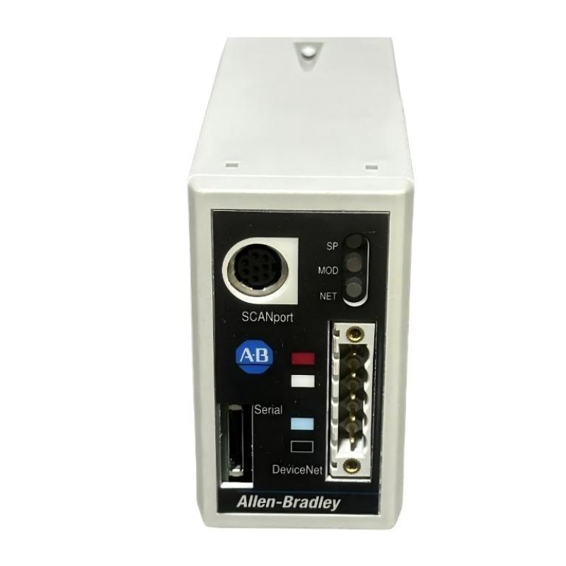
H2: Allen Bradley 1203-GU6 DeviceNet Module Overview
The 1203-GU6 is an enhanced DeviceNet communication module designed for high-speed PLC networks. It supports up to 64 nodes per network segment and provides real-time messaging for distributed I/O. Understanding its specifications is critical for reliable installation:
Voltage: 24V DC
Communication Rate: 125/250/500 kbps
Network Topology: Linear, star, or tree
Diagnostics: Built-in LED indicators and status registers
Real-case observation: in one setup, the module’s LED indicated a red fault due to bus voltage dropping below 22V, highlighting the importance of power supply verification before commissioning.
H2: Preparation for Allen Bradley 1203-GU6 Installation
Pre-installation checklist:
Verify network topology matches the project design.
Ensure proper DeviceNet cable (24 AWG twisted pair, shielded) and connectors.
Confirm PLC firmware compatibility with 1203-GU6.
Measure bus voltage at module terminals (should read 24V ± 5%).
Field experience tip: Always power the PLC and module separately during first setup to prevent cascading network errors.
H2: Wiring and System Configuration of 1203-GU6
Wiring mistakes are the most frequent cause of initial setup failure:
Node Address: Each 1203-GU6 must have a unique address; duplicate addresses result in immediate communication timeout.
Termination: Place 120Ω terminators at both ends of the network. Missing or loose terminators often trigger intermittent faults.
Shielding: Ground the shield at a single point to prevent noise-induced errors.
Real-case data: During a production line retrofit, improper shield grounding caused network errors every 5–10 minutes. After correctly grounding the shield, communication became stable, reducing error logs from 1200/hr to less than 5/hr.
H2: Commissioning Allen Bradley 1203-GU6 DeviceNet Module
Steps for commissioning:
Power on PLC and module while monitoring the status LEDs.
Load DeviceNet configuration using RSNetWorx.
Perform node scan and validate connectivity for all connected devices.
Record baseline signal quality and bus load metrics.
Field insight: During commissioning at a chemical plant, vibration and electrical noise caused occasional packet loss. Adjusting cable routing away from VFD cables resolved these intermittent errors.
H2: Validation and System Testing
Confirm successful message exchange between PLC and remote I/O.
Monitor bus load and error counters for at least 24 hours to ensure stability.
Document network parameters: node addresses, baud rate, and terminator placement.
Engineering note: Real-case observation shows that modules operating at 500 kbps in noisy industrial environments may require ferrite beads on cables to reduce EMI-induced errors.

