Allen-Bradley 1203-SM1 SLC to SCANport Communication Module Installation Guide
Time:2026-06-02 Browse: 9
The Allen-Bradley 1203-SM1 SLC to SCANport communication module is commonly misinstalled in legacy SLC-500 systems due to incorrect SCANport cabling, DIP switch configuration errors, or rack slot placement issues rather than actual hardware failure. In most commissioning cases, communication instability originates from network topology and scanport addressing, not the module itself.
This installation guide focuses on real engineering field practices used in SCANport-based drive integration systems.
<h2>1203-SM1 PLC System Role in SCANport Architecture</h2>
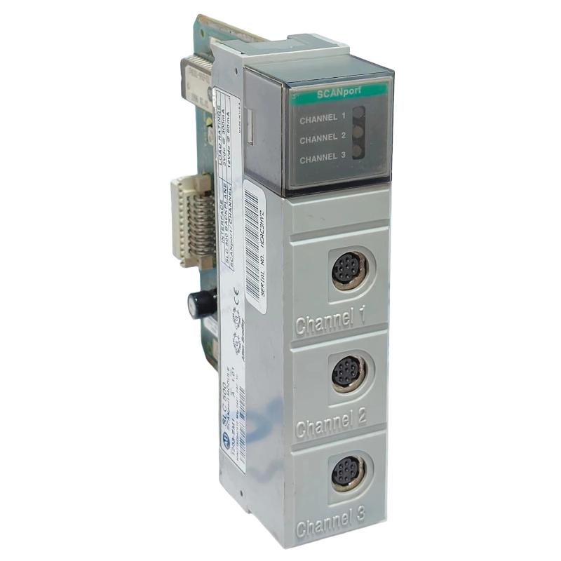
The 1203-SM1 acts as a SLC backplane to SCANport bridge module, enabling an Allen-Bradley SLC processor to control up to three SCANport-compatible devices such as legacy 1305 or 1336 drive systems.
From a control perspective, the module performs three critical tasks:
Translates SLC I/O image into SCANport command structure
Manages 16-bit logic command and feedback exchange
Maintains cyclic data transfer for drive references
In one retrofit project involving a SLC 5/03 controller, engineers observed that incorrect channel assignment caused intermittent drive enable failures, later traced to misconfigured scanport addressing rather than PLC logic.
<h2>Allen-Bradley 1203-SM1 Installation Preparation Checklist</h2>
Before physical installation, engineers typically verify:
SLC chassis slot availability (4, 7, 10, or 13-slot rack supported)
Minimum enclosure depth of 200 mm (critical in retrofit panels)
SCANport cable length not exceeding 10 meters total per segment
DIP switch configuration recorded from old module (if replacement case)
A common field mistake is assuming SCANport behaves like modern Ethernet-based networks. It does not—topology is strict point-to-point with limited branching rules.
<h2>1203-SM1 Wiring and SCANport Connection Strategy</h2>
Wiring errors account for over 60% of commissioning issues in SCANport systems.
Key wiring rules:
Channel 1–3 are independent SCANport buses
Each channel supports up to one device chain (max 10 m total cable length)
Daisy chaining must respect port termination rules
During a plant upgrade in a packaging facility, engineers found that a motor drive intermittently dropped out due to exceeding SCANport cable limits. After reducing the cable run from 14 m to 8 m, communication stabilized immediately without any module replacement.
<h2>1203-SM1 Commissioning and System Validation</h2>
Commissioning should be performed in three stages:
1. Backplane Verification
Ensure the SLC CPU recognizes the module in the I/O configuration. A missing module here often indicates rack power sequencing issues.
2. SCANport Device Enumeration
Verify each connected drive responds on its assigned channel. Basic mode should confirm:
Logic Command bits toggle
Feedback words return stable values
3. Functional Load Test
Apply low-speed reference commands and monitor:
Reference signal scaling
Feedback response delay
Drive enable response time
In a commissioning case with SLC 5/02, feedback jitter was observed (±3–5%). Root cause was traced to mixed basic/enhanced mode configuration mismatch.
<h2>Common Installation Pitfalls in 1203-SM1 Systems</h2>
Incorrect DIP switch node addressing
Mixing SCANport devices with incompatible firmware revisions
Overlooking enclosure depth requirement (causes overheating in dense panels)
Using non-certified SCANport cables
Installation Summary
The 1203-SM1 is highly reliable when installed with correct SCANport discipline. Most failures reported in the field are system integration issues, not module defects.

