Allen-Bradley 1321-M048 Common Mode Choke Installation Guide
Time:2026-06-03 Browse: 10
Allen-Bradley 1321-M048 common mode choke installation is typically required when engineers face EMI issues in VFD-driven motor systems rather than hardware incompatibility. In most real-world commissioning cases, interference problems are caused by cable layout, grounding topology, or PWM switching behavior, not the choke itself.
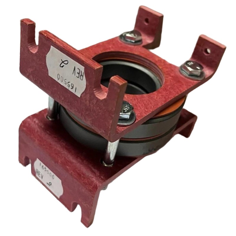
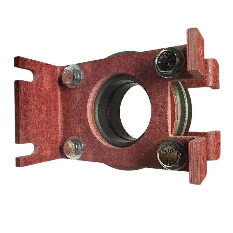
The 1321-M048 is a 48A open-style common mode choke designed for Rockwell/Allen-Bradley AC drives such as PowerFlex series. It is installed on the drive output side to suppress high-frequency common-mode noise generated by PWM switching.
Allen-Bradley 1321-M048 Common Mode Choke Application Overview
The choke is used in VFD systems to:
Reduce common-mode current leakage
Suppress EMI affecting PLC controllers and sensors
Improve system stability in long motor cable applications
Lower high-frequency voltage stress on motor insulation
In one commissioning case at a packaging plant, a PowerFlex 525 system showed intermittent analog signal drift on nearby PLC inputs. After installing the 1321-M048 at the inverter output, noise coupling dropped significantly and analog fluctuation reduced from ±120 mV to under ±20 mV.
Allen-Bradley 1321-M048 Installation Preparation (Engineering Checkpoint)
Before installation, engineers typically verify:
Drive output current ≤ 48A rated capacity
Motor cable length (recommended >15–20 m for effectiveness)
Proper PE grounding system (single-point grounding preferred)
Cabinet EMC layout separation between power and signal lines
A common field mistake is installing the choke too close to signal wiring bundles, which reduces its effectiveness.
Allen-Bradley 1321-M048 Wiring Configuration Strategy
The choke is non-polarized, meaning direction does not affect operation. However, layout discipline matters more than orientation.
Typical wiring structure:
VFD U/V/W → 1321-M048 input side
Choke output → motor U/V/W terminals
Key engineering rule:
Keep motor cable shield bonded 360° at both ends to maximize EMI suppression effectiveness.
In one site audit, improper shield termination caused persistent PLC communication faults even after choke installation. Correcting grounding resolved the issue without replacing hardware.
Allen-Bradley 1321-M048 Commissioning Procedure (Field Practice)
During system energization:
Run motor at no load first
Measure leakage current using clamp meter
Check motor frame voltage (<10V RMS recommended)
Monitor PLC analog noise stability
A typical result after correct installation:
Reduced HF noise on analog inputs
Lower motor bearing discharge current
Improved encoder signal stability
Allen-Bradley 1321-M048 Installation Validation Insight
From field experience, the choke does not eliminate EMI completely, but shifts the impedance profile of the system so that high-frequency common-mode components are attenuated.
If interference persists, engineers usually investigate:
PWM carrier frequency settings
Cable routing separation distance
Ground loop impedance
Missing motor output reactors (if applicable)
Allen-Bradley 1321-M048 Installation Summary (Engineering Note)
The 1321-M048 should be viewed as part of a system-level EMC strategy, not a standalone fix. Proper installation depends heavily on:
Drive output topology
Cable shielding quality
Grounding architecture
When applied correctly, it significantly improves PLC system stability, sensor integrity, and VFD-driven motor EMC performance.

