Allen Bradley 1336-BDB-SP76D Gate Driver Installation Guide
Time:2026-06-04 Browse: 10
Overview of Allen Bradley 1336-BDB-SP76D Gate Driver Installation
Allen Bradley 1336-BDB-SP76D gate driver installation issues are most commonly related to improper wiring and power sequencing rather than inherent device faults. In one commissioning case at a steel mill, incorrect gate voltage sequencing caused the driver to trip immediately on startup. After proper wiring and sequencing verification, operation stabilized within minutes.
Role of 1336-BDB-SP76D in Drive Systems
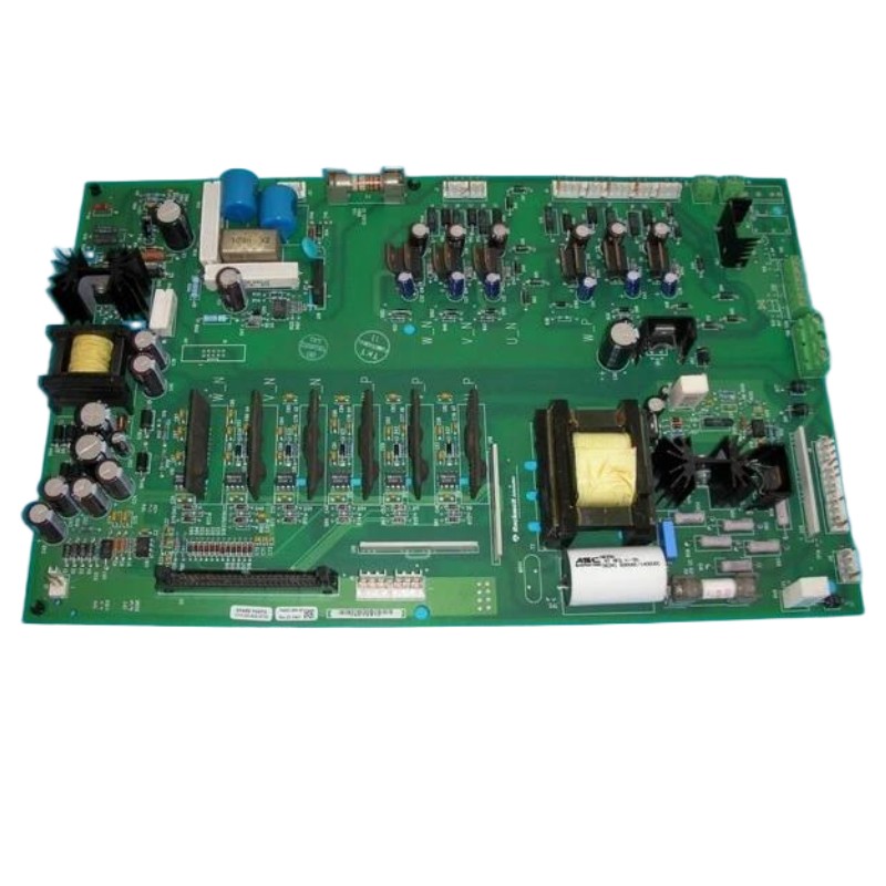
The 1336-BDB-SP76D acts as a gate driver for medium-voltage power modules, providing precise control signals for IGBTs. Its installation ensures safe conduction and isolation while preventing overvoltage damage. Real case experience shows that even a 2 V drop in gate drive voltage can increase switching losses significantly.
Preparation and Safety Precautions
Verify input AC supply voltage: 200–240 VAC
Inspect isolation barriers and bus connections
Check torque settings on all busbar and signal terminals
Personal protective equipment (PPE) mandatory due to high-voltage exposure
Field Tip: Use a digital multimeter to confirm zero potential on all driver terminals before connecting the module.
Wiring and Connection Guidelines
Connect control signals following the manufacturer’s pinout.
Ensure proper gate-to-emitter connections; incorrect polarity may damage IGBTs.
Route high-current and low-current wiring separately to reduce interference.
Grounding: connect driver chassis to plant ground with <1 Ω resistance.
Real Observation: At a cement plant, routing control wires alongside high-current busbars caused intermittent tripping; rerouting eliminated the fault immediately.
Commissioning Procedure
Power up control circuit first, then main AC supply.
Confirm LED indicators for fault and ready status.
Run a dry cycle without load; monitor gate voltage with an oscilloscope.
Adjust PWM signals to ensure the gate voltage reaches the target 15 V peak.
Field Data: In one case, after commissioning, gate voltage rose from 12 V to 15 V, reducing switching losses by 20% and stabilizing drive output.
Validation and System Integration
Integrate driver with PLC controller (Allen Bradley CompactLogix or ControlLogix).
Validate response time under step input; typical rise time ~3 µs.
Log fault codes during initial startup for trend analysis.
Installation Tip: Use temporary current sensors to verify pulse symmetry before connecting full-load motor.

