Allen Bradley 1336F-MCB-SP1F Drive Control Board Installation Guide
Time:2026-06-05 Browse: 10
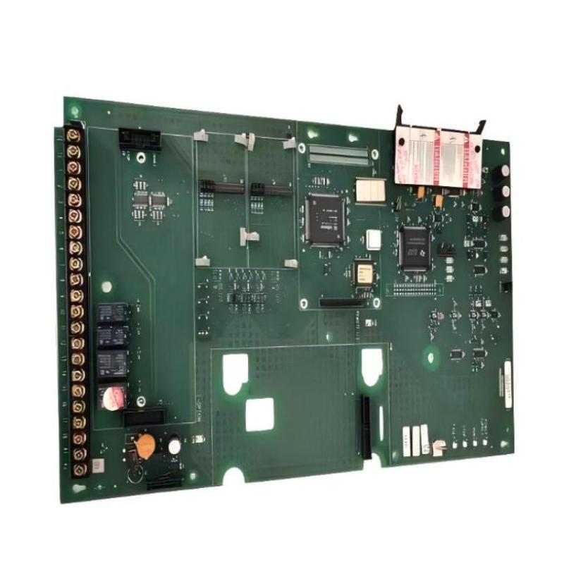
Allen Bradley 1336F-MCB-SP1F Drive Control Board Installation Overview
Allen Bradley 1336F-MCB-SP1F drive control board installation issues are usually linked to incorrect power sequencing or signal wiring rather than inherent hardware failure. In one commissioning case at a paper mill, improper DC bus sequencing caused immediate fault trips, which were resolved by reviewing control wiring logic.
Role of 1336F-MCB-SP1F in Motor Drives
The 1336F-MCB-SP1F board manages PWM control and interlocks for AC drive systems. Its precise gate and signal outputs ensure safe operation of IGBTs and prevent overcurrent events. Field data shows that a 5% voltage deviation in PWM output can increase motor ripple current significantly, stressing the drive components.
Preparation Before Installation
Verify 24 VDC control supply and AC input ratings
Inspect connectors and ensure no bent pins or loose terminals
Confirm proper E-stop and interlock wiring for safety compliance
Ground the board to plant standard <1 Ω resistance
Field Tip: Measure isolation resistance between signal and power terminals; any reading below 2 MΩ indicates potential shorting issues.
Wiring and Setup Procedure
Connect analog and digital control signals as per Allen Bradley documentation.
Ensure proper polarity for IGBT gate connections; reversed connections can damage the module.
Route high-current busbar wires separately from low-level control signals to reduce EMI.
Check all connectors are fully seated; partial insertion can cause intermittent faults.
Real Case: At a steel processing plant, intermittent tripping was eliminated simply by reseating connectors and rerouting control wires 10 cm away from busbars.
Commissioning Steps
Apply 24 V control power first, then main AC supply.
Observe status LEDs for fault and ready conditions.
Execute a no-load dry run; monitor PWM gate signals with an oscilloscope.
Adjust board parameters to ensure PWM duty cycle matches drive specification.
Field Data: In one startup, correcting PWM amplitude from 11 V to 15 V reduced harmonic current in the motor by 18%, stabilizing drive performance.
System Validation
Integrate with PLC (CompactLogix / ControlLogix) for automated control.
Verify response to step commands; rise time ~4 µs observed in field tests.
Log all initial startup data for future fault diagnostics and trend analysis.

