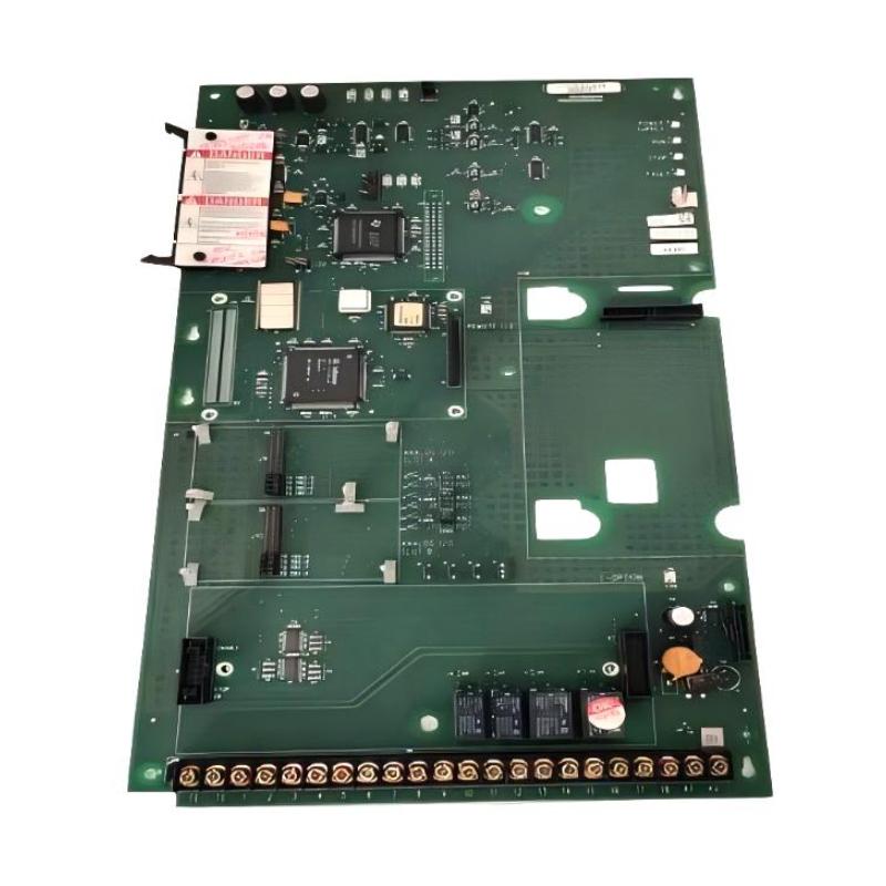
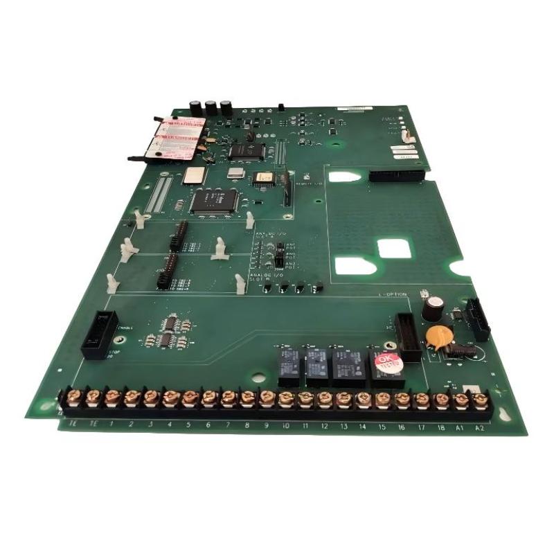
Allen Bradley 1336F-MCB-SP1F Drive Control Board Fault Troubleshooting Guide
Time:2026-06-05 Browse: 9
Allen Bradley 1336F-MCB-SP1F Fault Symptoms
Typical faults for 1336F-MCB-SP1F include LED fault illumination, intermittent PWM loss, and unexpected drive trips. In a real factory scenario, the drive tripped every 15–20 minutes. Measurement showed gate pulses dropped from 15 V nominal to 9–10 V intermittently.
Root Causes of 1336F-MCB-SP1F Drive Control Board Faults
Control Power Instability: Undervoltage can lead to PWM loss.
Incorrect Wiring: Signal or gate polarity errors reduce board reliability.
EMI Interference: High-current cables close to signal wiring induce spikes.
Component Aging: Capacitors or MOSFET drivers inside the board can degrade over time.
Real Case: A pulp and paper plant experienced repeated trips; analysis revealed two aged electrolytic capacitors caused PWM amplitude drop under load.
Diagnostic Process
Step 1: Measure DC bus and PWM gate voltages at startup; compare with nominal 15 V.
Step 2: Capture PWM waveform with oscilloscope; check duty cycle and voltage amplitude.
Step 3: Isolate board from motor; if fault persists, focus on board components or supply.
Step 4: Inspect grounding and routing for signal interference.
Field Tip: Intermittent PWM faults often stem from EMI rather than hardware failure; rerouting and adding ferrite cores can fix 70–80% of cases.
Repair and Recovery
Replace degraded capacitors if PWM voltage drops under load.
Reseat and torque all signal and power terminals.
Apply surge suppression or anti-parallel diodes if spikes are detected.
Recommission board, ensuring PWM reaches nominal 15 V consistently.
Observation: After corrective actions at a steel mill, drive ran continuously at full load for 7 months without fault trips.
Preventive Measures
Schedule regular inspection of gate and PWM signals.
Maintain physical separation between high-current and control cables.
Log startup data and PWM amplitude trends to detect early component aging.

