Honeywell 05701-A-0283 Single Channel Control Card Installation Guide (System Setup & Commission
Time:2026-06-08 Browse: 12
Honeywell 05701-A-0283 Single Channel Control Card Installation Overview
Honeywell 05701-A-0283 single channel control card installation issues are most often linked to incorrect loop wiring or improper sensor drive module seating rather than actual card failure. In a real refinery gas detection upgrade project, repeated “channel fault” alarms were traced back to reversed 4–20 mA loop polarity instead of hardware damage. Once corrected, the system stabilized immediately without component replacement.
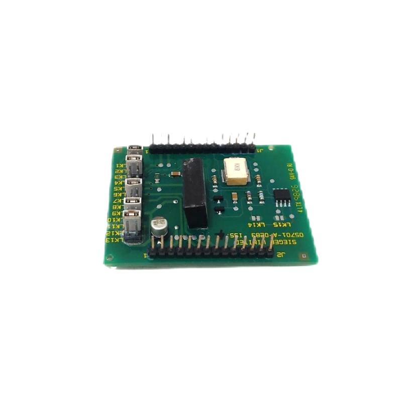
The 05701-A-0283 is a 4–20 mA sensor drive module used inside Honeywell System 57 / 5701 single channel control cards, responsible for sensor excitation and signal conditioning in gas detection loops.
Function Role of 05701-A-0283 in Single Channel Control System
The 05701-A-0283 module is not a standalone controller—it is the signal conditioning and sensor power stage inside the control card.
Its core functions include:
Providing excitation voltage to catalytic or 4–20 mA gas sensors
Converting raw sensor signals into a standardized loop output
Feeding processed data to the single channel control logic for alarm evaluation
From field experience, even small instability in this module directly affects alarm thresholds and can shift readings by 3–8% FSD.
Preparation Before Installation (Field-Level Checks)
Before inserting or commissioning the card:
Confirm +24 V DC supply stability (18–32 V operating range typical system level)
Inspect backplane connectors for oxidation or bent pins
Ensure sensor loop is isolated (avoid earth loop paths)
Verify correct module type: 05701-A-0283 (4–20 mA) vs catalytic variant
Engineering Note:
In one offshore platform commissioning case, intermittent “sensor fail” alarms were caused by a partial seating of the plug-in drive module—visually correct but electrically unstable.
Wiring Strategy for Stable Signal Acquisition
The 05701-A-0283 module connects through the control card backplane, but field wiring still determines signal integrity:
Keep 4–20 mA loop cables shielded and grounded at one end only
Avoid running signal cables parallel to high-voltage relay lines
Maintain separation between sensor loop and ignition power circuits
Ensure correct polarity on loop terminals (S / NS configuration dependent on system variant)
Real Case Observation:
At a chemical plant, signal drift of ~12% was traced to cable shielding grounded at both ends, creating a loop current distortion.
Commissioning Procedure (System Behavior Validation)
Commissioning should focus on signal behavior, not just power-up status:
Apply control card supply power and confirm LCD initialization
Monitor sensor loop output (expect stable 4–20 mA range)
Trigger controlled gas simulation or calibration gas injection
Verify alarm thresholds (A1 / A2 / A3) respond correctly
Check relay activation timing under alarm conditions
Field Data Example:
After correct commissioning in a refinery gas monitoring system, signal stability improved from ±9% fluctuation to under ±2%, significantly reducing nuisance alarms.
System Integration Validation
Confirm communication with relay/field interface cards (e.g., 05701-A-0326 series)
Verify alarm status propagation to system controller
Test fault self-diagnosis behavior during simulated sensor disconnection
A properly installed 05701-A-0283 module should show stable loop feedback and zero intermittent fault LEDs during steady-state operation.

