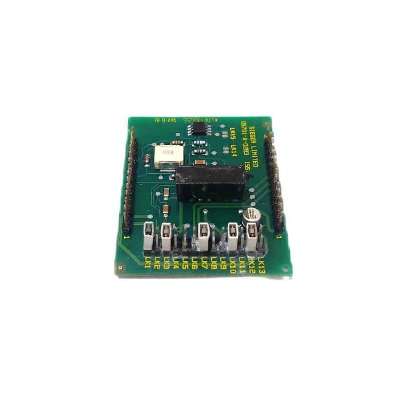
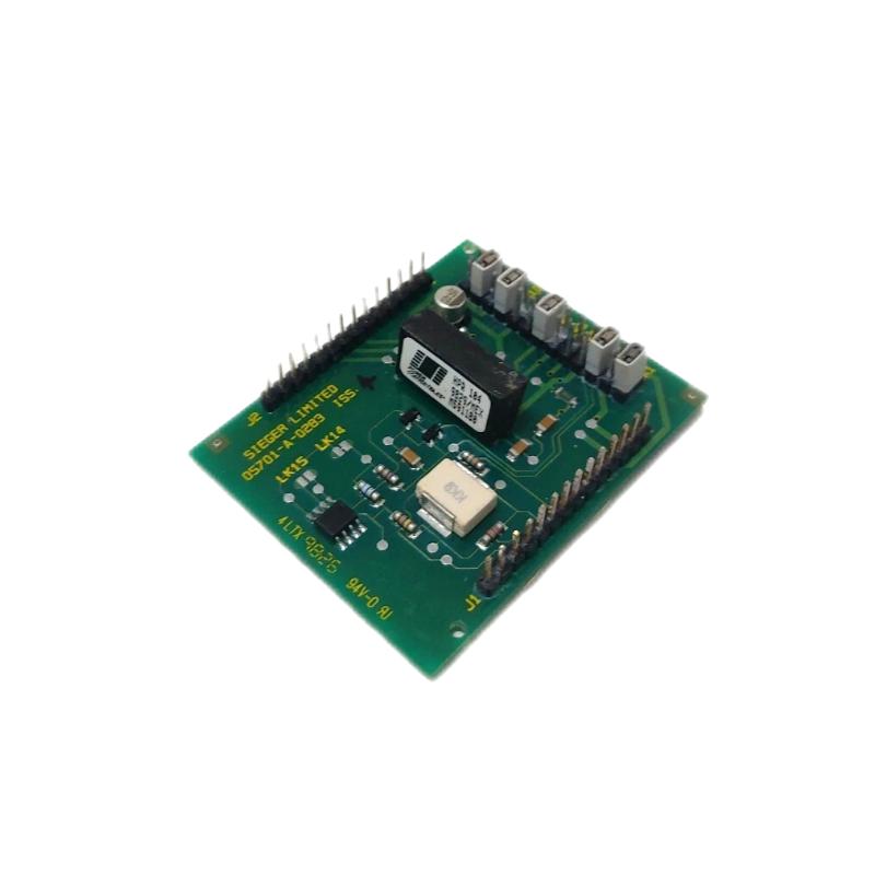
Honeywell 05701-A-0283 Single Channel Control Card Fault Troubleshooting Guide (Signal & Loop Di
Time:2026-06-08 Browse: 12
Honeywell 05701-A-0283 Fault Symptoms in Single Channel Control System
When Honeywell 05701-A-0283 related faults occur, they typically present as:
Channel “FAULT” LED active without sensor failure
Intermittent 4–20 mA signal dropouts
Unstable gas reading under constant environmental conditions
False alarm triggering at low concentration levels
In a LNG terminal monitoring system, repeated high alarms occurred even under zero gas conditions, creating suspicion of sensor contamination. However, diagnostics showed the sensor drive output was unstable rather than the detector itself.
Root Cause Analysis of 05701-A-0283 Failures
Unlike field sensors, this module’s failures are usually electrical or signal-chain related:
1. Sensor Drive Instability
Aging internal components can cause unstable excitation voltage to the sensor, leading to fluctuating output current.
2. Loop Impedance Mismatch
Incorrect loop resistance causes distorted 4–20 mA scaling and false alarm interpretation.
3. Backplane Contact Degradation
Oxidized connectors between module and control card introduce micro-interruptions.
4. External EMI Interference
High-power switching equipment nearby can inject noise into the signal conditioning circuit.
Real Case:
At a petrochemical facility, a nearby VFD drive induced transient spikes that caused the module output to oscillate between 12 mA and 18 mA unexpectedly.
Diagnostic Workflow (Engineering Approach)
A structured troubleshooting process is critical:
Step 1: Measure Loop Current Stability
Use a calibrated loop meter to observe real-time 4–20 mA behavior.
Stable = flat signal line
Fault = jittering ±2–6 mA variations
Step 2: Isolate Sensor vs Module
Disconnect sensor input and simulate loop signal.
If fault persists → module or backplane issue
If cleared → sensor or field wiring issue
Step 3: Check Backplane Contact Resistance
Measure resistance across module seating points. Anything above a few milliohms suggests poor contact.
Step 4: Evaluate EMI Environment
Inspect proximity of:
VFD cables
High current switching relays
Motor starters
Repair Strategy and Field Recovery
Depending on diagnostic results:
Clean and reseat sensor drive module
Replace aging electrolytic components if voltage instability is confirmed
Re-route loop wiring away from power circuits
Add shielding or ferrite suppression if EMI is detected
Recalibrate 4–20 mA scaling after repair
Field Recovery Case:
After replacing a degraded sensor drive module in a refinery gas detection system, loop stability improved from ±5 mA fluctuation to ±0.3 mA, eliminating all false alarms.
Preventive Maintenance Recommendations
Perform quarterly loop current verification
Inspect backplane connectors during shutdown cycles
Maintain strict single-point grounding for loop shielding
Log alarm drift patterns for early detection of module degradation
A well-maintained 05701-A-0283 system typically maintains stable operation for years, provided EMI and wiring discipline are strictly controlled.

