Allen Bradley 1336F-MCB-SP1F Drive Control Board Installation Guide
Time:2026-06-09 Browse: 16
Allen Bradley 1336F-MCB-SP1F Drive Control Board Installation Overview
Allen Bradley 1336F-MCB-SP1F drive control board installation problems are typically caused by DC bus sequencing errors or improper backplane seating rather than actual PCB failure. In a real retrofit project on a 1336 PLUS II drive system, the unit repeatedly showed “Main Control Fault” immediately after power-up. The root cause was not the board itself but an un-discharged DC bus capacitor causing unstable initialization voltage.
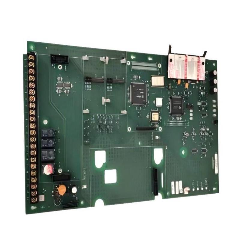
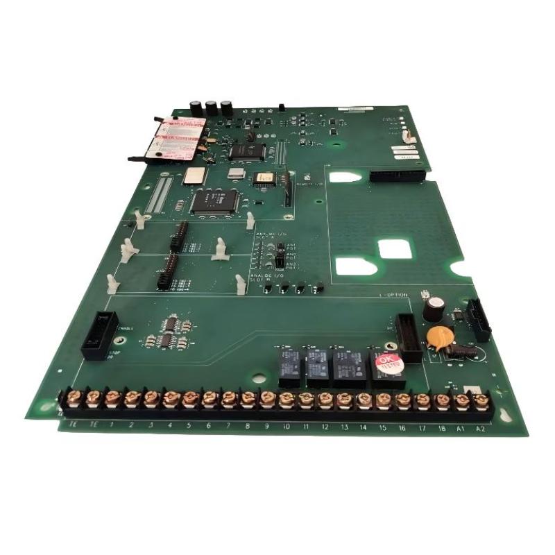
The 1336F-MCB-SP1F is the main control board for Allen-Bradley 1336 PLUS II variable frequency drives, responsible for coordinating PWM generation, I/O logic, and communication interface between control layers and inverter stages.
1336F-MCB-SP1F Drive Control Board Functional Role in 1336 PLUS II System
The 1336F-MCB-SP1F is not a passive interface board—it is the central execution layer of the drive system.
Key functions include:
PWM control coordination for inverter switching stages
Processing analog/digital reference signals (0–10V, 4–20mA inputs)
Managing fault logic (overcurrent, undervoltage, stall conditions)
Handling HIM interface and communication adapters
From field observation, instability in this board often appears as random frequency fluctuation even when the speed reference is stable, indicating control loop disturbance rather than motor-side issues.
Pre-Installation Engineering Checks (Critical for Reliability)
Before installing or replacing the 1336F-MCB-SP1F:
Confirm DC bus is fully discharged (measure below safe voltage threshold)
Verify correct frame compatibility (B–G series drives)
Inspect J2/J4 jumper connectors for oxidation or mechanical deformation
Check TB2 terminal block integrity (loose terminals are a frequent failure trigger)
Field Note:
In one commissioning case, a drive board was replaced twice before engineers discovered a partially discharged bus capacitor was re-energizing the control rail during installation.
Installation Logic and Wiring Strategy
Unlike modern modular drives, the 1336F-MCB-SP1F relies heavily on backplane signal integrity.
Key installation principles:
Seat board evenly into mounting plate before tightening screws
Torque mounting screws uniformly (avoid PCB flex stress)
Connect TB2 control wiring only after mechanical seating is confirmed
Keep HIM and adapter cables fully latched to avoid intermittent resets
Real Case Observation:
At a packaging plant, intermittent “Serial Fault” events were traced to a slightly lifted board edge—mechanically stable but electrically unstable under vibration.
Commissioning Procedure (System-Level Validation)
Commissioning should focus on control stability rather than simple startup confirmation:
Apply control power first (logic rail stabilization check)
Confirm HIM display initialization and no background faults
Inject low-frequency reference signal (5–10 Hz)
Observe output waveform stability via motor current signature
Increase load gradually and monitor PWM response consistency
Field Data Example:
After correct installation, one steel mill drive reduced output ripple from ~8% to under 2%, significantly improving motor torque stability during low-speed operation.
System Validation and Integration
Verify PLC speed reference consistency (analog or network input)
Confirm relay output CR1/CR2/CR3 transitions correctly
Run step-load test under 25%, 50%, 100% load conditions
Log fault memory for first 24-hour operational cycle
A properly installed 1336F-MCB-SP1F should show stable frequency output with no spontaneous reset or watchdog faults under thermal load variation.

