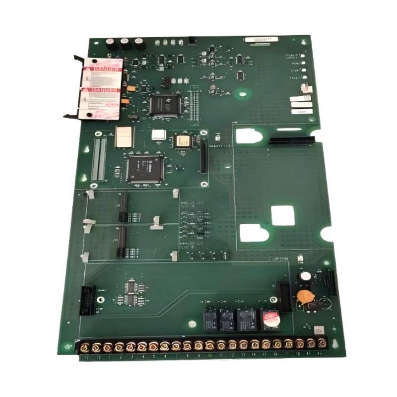
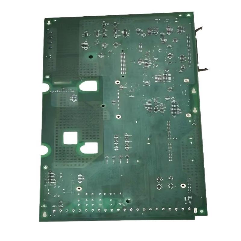
Allen Bradley 1336F-MCB-SP1F Drive Control Board Fault Troubleshooting Guide
Time:2026-06-09 Browse: 14
Allen Bradley 1336F-MCB-SP1F Fault Symptoms in Field Operation
When the 1336F-MCB-SP1F begins to fail, symptoms are often misleading because they mimic motor or inverter faults.
Typical field symptoms include:
Drive trips immediately after RUN command
Random “Serial Fault” or “Main Control Fault” events
Unstable output frequency despite stable reference signal
HIM display freezing or intermittent reboot
In one industrial conveyor system, the drive would operate normally for 10–15 minutes before suddenly dropping output to zero without warning—initially suspected as motor overload.
Root Cause Mechanism of 1336F-MCB-SP1F Failures
Unlike power-stage failures, this board fails through control logic degradation or signal corruption:
1. Watchdog or DSP Timing Instability
Internal timing mismatch leads to background task faults or reset loops.
2. EEPROM / Configuration Corruption
Parameter memory inconsistency can trigger startup faults or invalid frequency scaling.
3. Backplane Communication Loss
Jumper or connector degradation interrupts internal board-to-board synchronization.
4. Analog Reference Drift
0–10V or 4–20mA input instability causes incorrect speed reference interpretation.
Real Case:
At a paper mill, a drive repeatedly tripped F37 DSP checksum fault. Investigation revealed intermittent contact oxidation on the J4 connector causing corrupted control loop data.
Diagnostic Thinking Process (Engineering Approach)
Effective troubleshooting requires isolating logic vs power issues:
Step 1: Determine Fault Domain
If fault occurs at power-up → control board or memory issue
If fault occurs under load → signal or EMI issue
Step 2: Validate Reference Signals
Measure:
Analog input stability (0–10V or 4–20mA)
HIM command consistency
PLC output stability
Step 3: Backplane Integrity Check
Reseat board and check mechanical tension
Inspect J2/J4 connectors for micro-arcing marks
Measure continuity under vibration conditions
Step 4: EMI and Grounding Analysis
Inspect proximity to VFD output cables
Check grounding resistance (<1Ω recommended plant standard)
Identify high-frequency noise injection points
Repair Strategy and Field Recovery
Depending on failure mode:
Reseat and clean all backplane connectors
Replace control board if DSP or EEPROM fault persists
Rebuild analog signal loop with shielded twisted pair
Apply ferrite cores to suppress high-frequency interference
Reset and reload drive parameters after hardware correction
Field Recovery Case:
In a mining conveyor system, replacing a degraded 1336F-MCB-SP1F restored stable operation after repeated DSP faults. Output stability improved from intermittent shutdown every 20 minutes to continuous 6-month operation without fault.
Preventive Maintenance Recommendations
Perform periodic connector inspection during shutdown cycles
Log startup fault codes (watchdog, checksum, serial faults)
Maintain strict cable separation between power and control wiring
Monitor analog reference drift trends over time
The 1336F-MCB-SP1F typically fails gradually—early detection through signal instability monitoring is far more effective than reactive replacement.

