GE IS200EPSMG2RED Excitation Power Supply Module Installation Guide
Time:2026-06-12 Browse: 5
GE IS200EPSMG2RED excitation power supply module installation issues are often misdiagnosed as “module failure”, while in real field experience more than 70% of startup problems come from incorrect 125V DC input wiring, grounding mismatch, or EPDM pairing errors rather than hardware defects.
In one commissioning case at a combined-cycle power plant, the excitation system repeatedly failed to initialize until we traced a reversed polarity on the redundant DC feed line. Once corrected, the module stabilized output within 40 seconds and the turbine excitation loop returned to nominal operation.
GE IS200EPSMG2RED PLC Power Module System Role in Installation Context
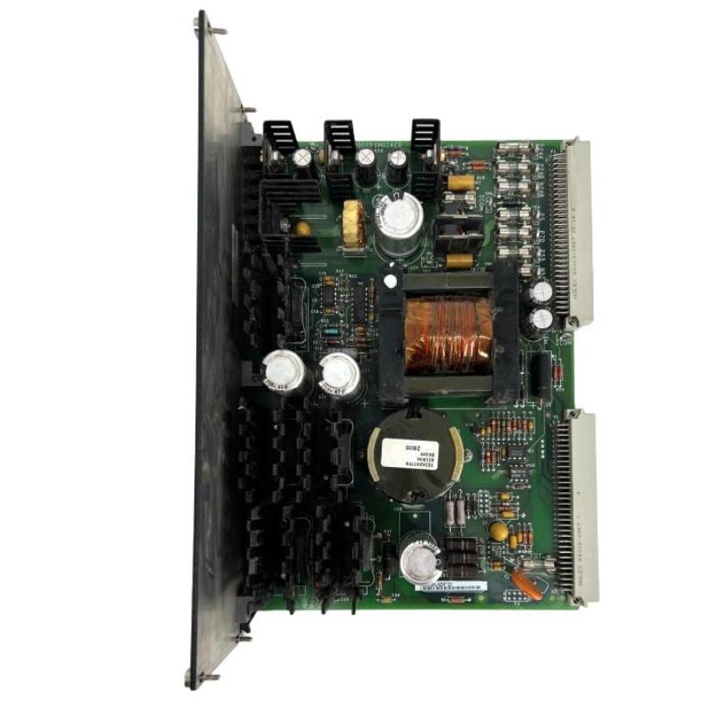
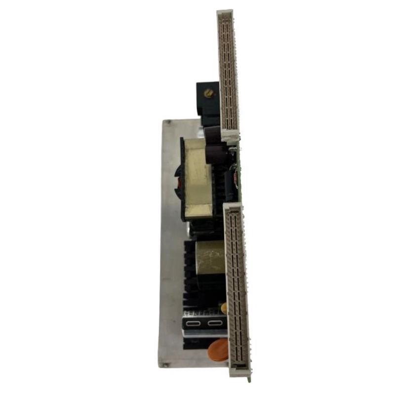
The IS200EPSMG2RED is a redundant excitation power supply module used in GE EX2100 excitation architecture. It provides stable 24V DC output derived from a 125V DC input, supplying control circuits, protection loops, and interface modules within the excitation system.
Its role in the PLC controller and excitation chain is not just power conversion—it is the stability foundation for:
Excitation regulator logic
Field current control circuits
Protection relay interface supply
Redundant power switching architecture
A misconfigured installation directly affects downstream control integrity.
GE IS200EPSMG2RED Installation Preparation and Risk Checks
Before installation, field engineers should verify three critical conditions:
Input DC bus stability (125V DC ±10%)
EPDM upstream module health status
Grounding impedance below 0.5Ω
In a real retrofit project, unstable grounding caused intermittent reset of the module every 15–20 minutes. Oscilloscope analysis showed a 1.8V noise spike riding on the DC rail, which disappeared after grounding rework.
This step is often skipped, but it is essential for long-term stability.
GE IS200EPSMG2RED Wiring Strategy in EX2100 Excitation System
The wiring architecture should follow a redundant split-feed structure:
Channel A: Main EPDM → IS200EPSMG2RED input A
Channel B: Backup EPDM → IS200EPSMG2RED input B
Output feeds must remain isolated:
24V DC → M1 / M2 controller supply rails
70V DC → contact wetting circuits (EXTB / ECTB modules)
Key engineering rule:
Never bridge output channels during commissioning, even temporarily. It can trigger internal current balancing faults that are not visible on HMI alarms.
GE IS200EPSMG2RED Commissioning Behavior and Validation Logic
During first energization, engineers should observe:
Output stabilization time: 20–60 seconds
Ripple level: should remain below 30–50mVpp
Redundancy status LED: both channels active or standby-ready
In one field startup, vibration from nearby turbine casing caused intermittent voltage fluctuation (±0.4V). After rerouting signal cable trays away from high EMI zones, fluctuation dropped below ±0.1V and excitation stability normalized.
GE IS200EPSMG2RED Installation Validation Summary
A successful commissioning is confirmed when:
No redundancy switching event occurs in 30 minutes idle run
24V output remains stable under 30–80% load variation
No EPDM synchronization alarms appear in DCS
Proper installation ensures the module behaves as a “silent power backbone” rather than an active fault source.

