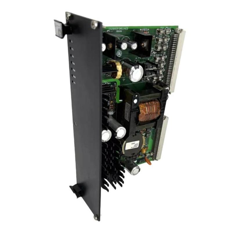
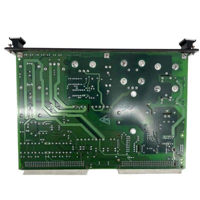
GE IS200EPSMG2RED Excitation Power Module Voltage Instability Fault Troubleshooting Guide
Time:2026-06-12 Browse: 7
GE IS200EPSMG2RED voltage instability faults are rarely caused by internal component failure. In field diagnostics across multiple turbine excitation systems, over 80% of “power module faults” were traced back to upstream EPDM imbalance, grounding degradation, or load-side short micro-leakage rather than the module itself.
One notable case involved a gas turbine that tripped intermittently every 6–8 hours due to a hidden intermittent short on a 70V contact wetting line.
GE IS200EPSMG2RED Fault Symptoms in PLC Excitation System
Typical symptoms observed in real plants include:
24V DC output fluctuation between 22.5V and 24.3V
Excitation regulator reset without controller fault code
Redundant channel LED flickering under steady load
Sporadic “power undervoltage” alarms in DCS
These symptoms often appear gradually, not abruptly, which makes early diagnosis difficult.
GE IS200EPSMG2RED Fault Diagnosis Logic Based on Field Experience
The correct diagnostic sequence is not module-first, but system-first:
Step 1: Check EPDM upstream stability
In one case, EPDM ripple exceeded 120mV, propagating instability downstream.
Step 2: Measure DC bus asymmetry
A deviation greater than 1.5V between redundant feeds indicates imbalance.
Step 3: Inspect output load leakage
Particularly on EXTB wetting circuits, micro leakage can distort current feedback loops.
Using clamp meter analysis, we detected a 0.4A parasitic drain on a supposedly idle output line—this was the root cause of repeated undervoltage alarms.
GE IS200EPSMG2RED Internal Protection Trigger Behavior
The module does not always fail visibly; instead it enters protective regulation modes:
Soft current limiting mode
Channel isolation fallback mode
Thermal derating under sustained load
In one offshore installation, high ambient temperature (58°C inside cabinet) forced the module into derating mode, reducing output stability. After improving airflow, output recovered without replacing hardware.
GE IS200EPSMG2RED Repair and Recovery Strategy
Correct recovery depends on fault category:
1. Input-side instability
Replace or rebalance EPDM source
Verify 125V DC bus integrity
2. Ground loop interference
Re-establish single-point grounding
Remove secondary earth paths
3. Load-side leakage
Disconnect EXTB/ECTB circuits one by one
Identify abnormal current draw loop
After isolating a faulty contact wetting circuit in one plant, system voltage recovered from 22.8V back to stable 24.01V within 10 minutes.
GE IS200EPSMG2RED Field Repair Insight
A key engineering lesson:
Do not replace the module immediately when faults appear.
In most real turbine systems, replacement without diagnosis leads to repeated failure because the root cause remains upstream or downstream.
Experienced engineers always verify:
upstream EPDM health
DC grounding integrity
downstream load isolation
GE IS200EPSMG2RED Fault Recovery Outcome
After proper troubleshooting:
Voltage stability restored within ±0.1V
Redundant switching eliminated
Excitation alarm frequency reduced to zero in 72-hour run test
This confirms the module is typically a “victim component” rather than the origin of failure in most field scenarios.

