Installation Article Schneider 140MSC10100 Single Axis Motion Module Installation Guide
Time:2026-06-15 Browse: 8
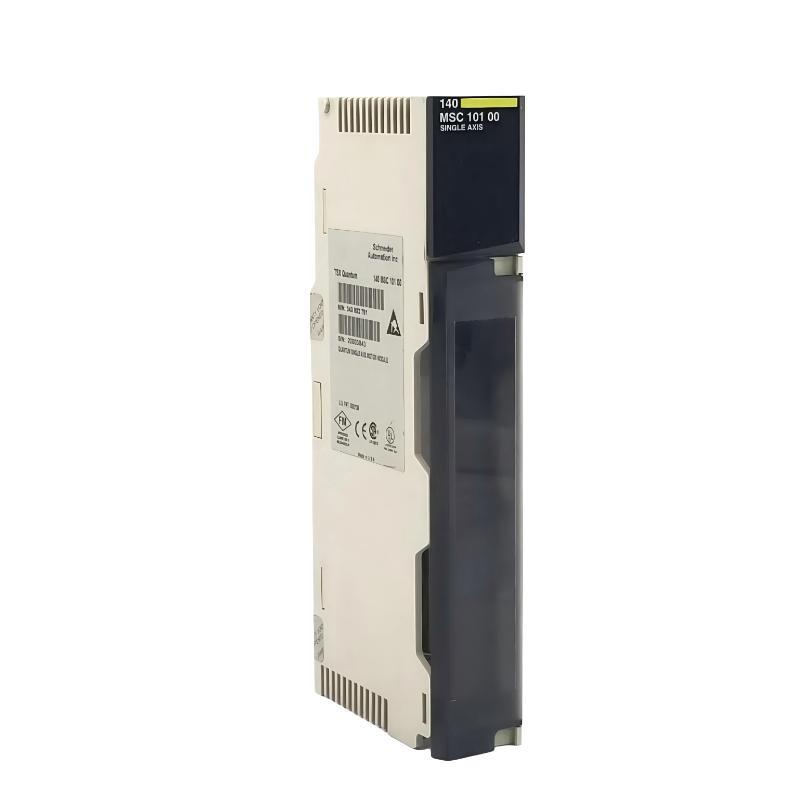
Schneider 140MSC10100 single axis motion module installation issues are usually not caused by hardware defects, but by incorrect backplane configuration, encoder wiring mismatch, or improper Quantum PLC system integration. In most field cases, commissioning failure happens during system initialization rather than final motion tuning.
This module is widely used in Modicon Quantum PLC architectures for high-precision single-axis motion control, including positioning, synchronization, and velocity regulation.
<h2>Schneider 140MSC10100 PLC Module System Role in Motion Architecture</h2>
The 140MSC10100 acts as a dedicated motion controller integrated into the Quantum backplane, responsible for:
Single-axis motion execution (1 real axis + 1 virtual/remote axis)
Encoder-based closed-loop feedback control
Positioning, homing, and cam profiling operations
Coordination with servo drives via high-speed control loops
In one packaging line project, we observed that replacing a generic PLC pulse output with this module reduced positioning deviation from ±1.8 mm to ±0.2 mm immediately after commissioning.
<h2>Schneider 140MSC10100 Installation Preparation and System Checks</h2>
Before installation, engineers should verify:
Quantum rack backplane integrity
5V differential encoder compatibility
Grounding resistance (< 1Ω recommended in industrial cabinet)
Slot allocation consistency in Unity/Control Expert configuration
A common mistake in the field is assigning incorrect rack slot mapping. In one commissioning case, the module was physically installed correctly, but the PLC configuration referenced slot 3 instead of slot 5, causing persistent “module not recognized” status.

<h2>Schneider 140MSC10100 Wiring and Encoder Interface Setup</h2>
The module uses a 5V differential encoder input, and wiring errors are one of the top installation failures.
Key wiring rules:
Use shielded twisted pair cables only
Shield must be grounded at one end only (control cabinet side)
Encoder A/B signals must not be reversed
Maintain separation from VFD output cables (>30 cm minimum)
We once saw unstable position feedback where signal noise introduced ±200 counts jitter. After re-routing encoder cables away from a 22kW inverter line, signal stability improved immediately.
<h2>Schneider 140MSC10100 Commissioning and First Power-On Behavior</h2>
During first startup:
Check LED status indicators (power / bus / fault)
Verify backplane communication handshake
Confirm encoder pulse detection in diagnostic mode
A typical commissioning sequence failure occurs when PLC logic starts motion before encoder initialization completes. This results in intermittent “axis not ready” faults.
In field experience, adding a 2–3 second delay after module initialization resolved 90% of early-stage commissioning alarms.
<h2>Schneider 140MSC10100 Installation Validation Strategy (Field Method)</h2>
A practical validation method used in real projects:
Command low-speed jog (10–20% speed)
Monitor encoder feedback consistency
Compare commanded vs actual position drift
Run homing cycle three times consecutively
If deviation remains under 0.05% after repeated homing, installation is considered stable.

