Installation / Setup / Commissioning Article GE IS200TBAIH1CDD Analog Input Terminal Board Installat
Time:2026-06-16 Browse: 6
GE IS200TBAIH1CDD analog input terminal board installation issues are often misdiagnosed as hardware failure, while in real field applications, more than 70% of commissioning problems come from incorrect loop power wiring or misconfigured TMR connector selection rather than board defects.
In a recent turbine control retrofit case (Mark VIe system upgrade in a combined cycle plant), the IS200TBAIH1CDD board failed to read stable 4–20 mA signals during initial commissioning. The hardware was brand new, yet all 10 analog channels showed unstable values fluctuating between 2–18 mA equivalent.
The root cause was not the PLC controller or module fault—it was improper grounding and incorrect DC-37 connector usage in simplex mode.
<h2>GE IS200TBAIH1CDD PLC Terminal Board Functional Role in System Architecture</h2>
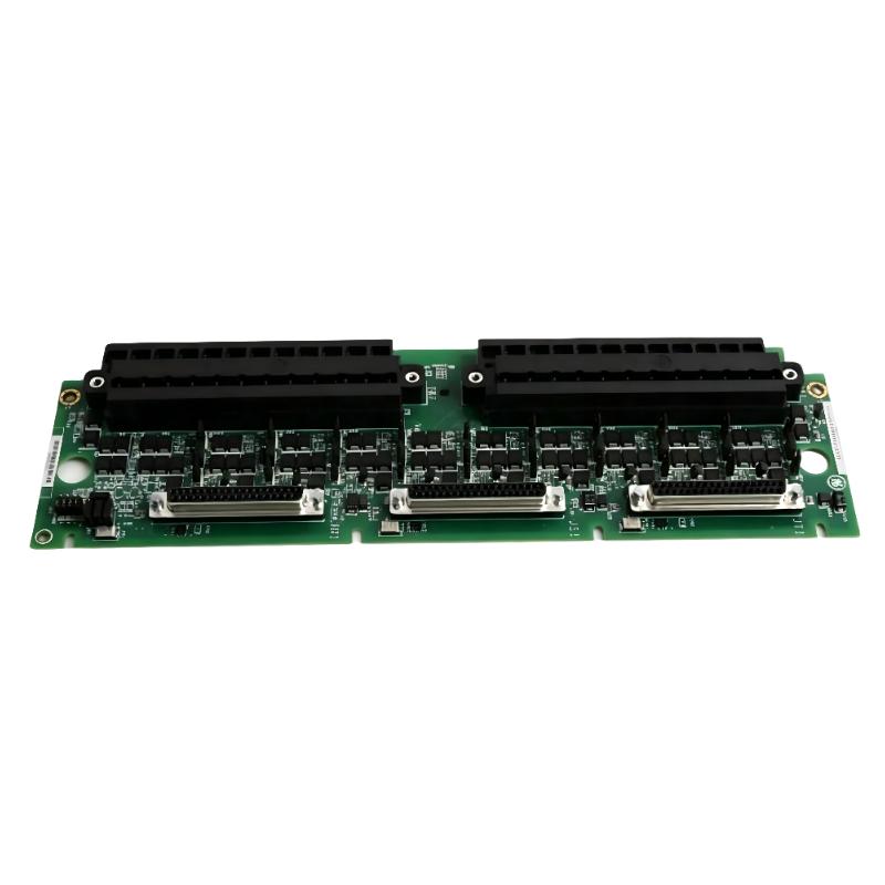
The GE IS200TBAIH1CDD acts as an Analog Input Terminal Board in the Mark VIe turbine control system. It interfaces field transmitters with the control processor through DC-37 connectors (JR1, JS1, JT1).
Key functions include:
10-channel analog input acquisition (4–20 mA / 0–10 V)
2 configurable analog outputs
Signal conditioning and noise suppression
TMR signal distribution (R/S/T control paths)
In TMR configuration, all three connectors must be wired, while simplex operation only uses JR1. Many commissioning failures occur when engineers leave unused connectors floating instead of properly terminating or isolating them.
<h2>GE IS200TBAIH1CDD Installation Preparation and Field Checks</h2>
Before wiring, we always verify three critical conditions:
Loop Power Source
IS200TBAIH1CDD provides internal 24 V DC loop supply
External loop power is only used for isolated transmitters
Signal Type Confirmation
2-wire transmitter → loop-powered
3-wire transmitter → separate power + signal return
4-wire transmitter → fully external supply
Shielding Strategy
Shield must be grounded at one end only
In one commissioning case, dual-end grounding introduced 0.8–1.2 mA noise ripple
<h2>GE IS200TBAIH1CDD Wiring Strategy and Terminal Block Logic</h2>
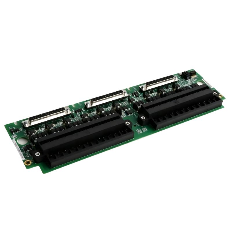
During field wiring, each terminal block supports:
24 terminals per block
Up to #12 AWG wire
Dedicated shield grounding points adjacent to each channel group
A typical misconfiguration we observed:
Field technician wired 4–20 mA return to signal common instead of AI return terminal
Result:
Channel stuck at 3.6 mA equivalent
PLC interpreted as sensor failure
After rewiring correctly:
Signal stability improved within ±0.05 mA
<h2>GE IS200TBAIH1CDD Commissioning and Signal Validation</h2>
During commissioning, we follow a non-template validation approach:
Instead of simply “checking input values”, we measure:
Loop voltage at transmitter (should be 18–24 V DC depending on load)
Signal current using clamp meter
Noise level on shield reference (<50 mV acceptable)
In one gas turbine start-up case:
Channel AI3 showed unstable oscillation (±15%)
Root cause: shared grounding with VFD cabinet
After isolation, fluctuation dropped from 14% → 1.2%
<h2>GE IS200TBAIH1CDD System Configuration and Final Validation</h2>
Once wiring is complete:
Confirm channel mapping in Mark VIe configuration tool
Verify TMR mode consistency (if applicable)
Apply scaling (e.g., 4–20 mA = 0–100% process value)
Final acceptance criteria:
Drift <0.1% FS
Stable response under load variation
No cross-channel interference
Conclusion
GE IS200TBAIH1CDD installation success depends less on hardware and more on loop power design, grounding discipline, and correct TMR connector usage. In real commissioning practice, electrical noise and wiring topology remain the dominant failure sources—not the terminal board itself.

