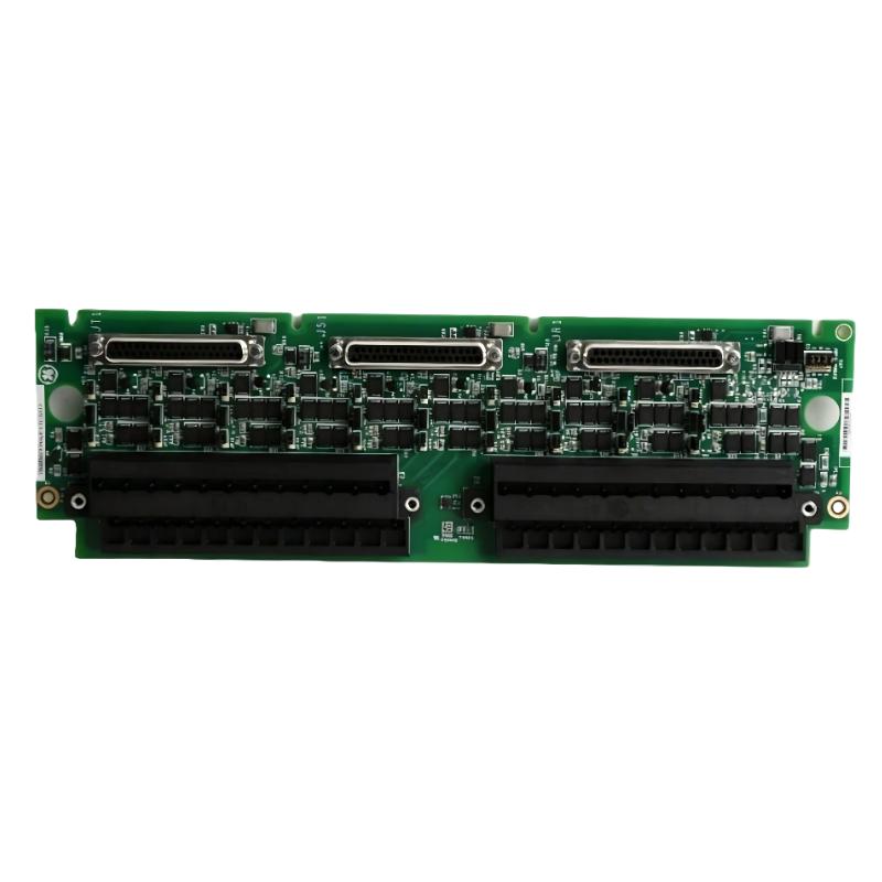
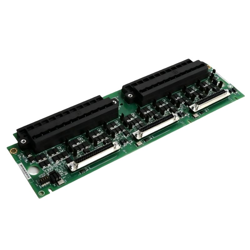
Fault / Troubleshooting Article GE IS200TBAIH1CDD Analog Input Fault Diagnosis Guide
Time:2026-06-16 Browse: 7
GE IS200TBAIH1CDD analog input faults are frequently misinterpreted as module failure, but in real turbine control field diagnostics, most issues originate from loop power instability, shielding defects, or DC-37 connector signal imbalance in TMR mode.
In a recent field case at a gas turbine plant, operators reported “random analog signal dropouts” across multiple channels. Initially, the maintenance team suspected a defective terminal board. However, deeper diagnostics revealed a completely different root cause: intermittent 24 V loop collapse due to a shared PSU overload with solenoid valves.
<h2>GE IS200TBAIH1CDD Analog Input Fault Symptoms in PLC System</h2>
Typical field-observed symptoms include:
Analog values freezing at 0% or 100%
Sudden jump between 4 mA and 20 mA equivalent
Channel mismatch between redundant TMR paths
Slow drift under constant process conditions
Intermittent signal loss on specific channels only
One critical diagnostic clue:
If only 2–3 channels fail while others remain stable, the issue is almost never the board hardware itself.
<h2>GE IS200TBAIH1CDD Fault Scenario: Intermittent Channel Dropout in TMR Mode</h2>
Case Observation
In one combined-cycle plant:
Channels AI1–AI10 randomly dropped to zero
Fault occurred only during turbine load ramp-up
No hardware alarms from Mark VIe system
Initial assumption:
Faulty IS200TBAIH1CDD board
Actual measured data:
Loop voltage dropped from 22.8 V → 17.2 V during load increase
Noise spike observed on shield reference (up to 180 mV)
This immediately redirected diagnosis away from PLC module failure.
<h2>GE IS200TBAIH1CDD Root Cause Analysis (Engineering Logic)</h2>
The failure chain was reconstructed as follows:
Load increase activated multiple solenoid valves
Shared 24 V DC power supply experienced voltage sag
Analog transmitters lost loop stability below ~18 V
Output current collapsed intermittently
PLC interpreted as sensor failure (not power failure)
Key insight:

