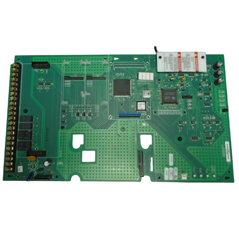
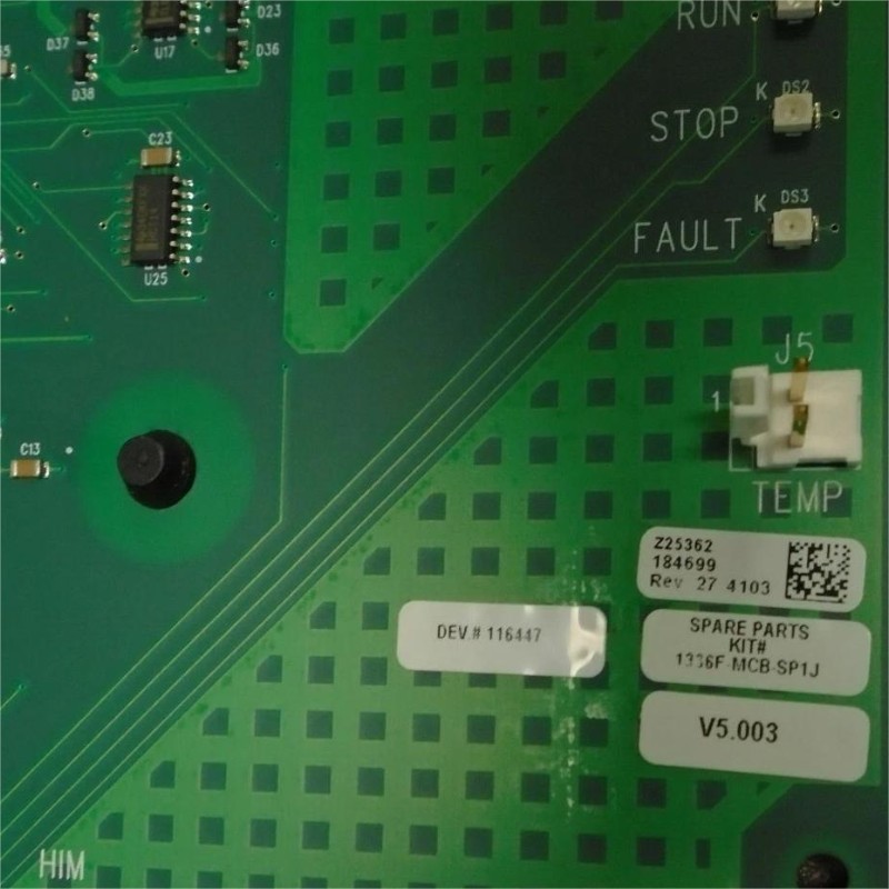
Allen-Bradley 1336F-MCB-SP1J Drive Control Board Installation Guide
Time:2026-06-18 Browse: 8
The 1336F-MCB-SP1J control board installation is often misdiagnosed as a “plug-and-play replacement”, but in real field commissioning cases, most startup failures come from incorrect grounding, loose J2/J4 interface seating, or corrupted parameter transfer during power-up, not from the board itself.
In one retrofit job on an Allen-Bradley 1336F drive controlling a 55kW conveyor line, the system failed to run after a control board swap even though the new module was fully functional. The issue was traced to missing shield grounding on the SCANport communication loop, causing unstable reference signals during initialization.
<h2>Allen-Bradley 1336F-MCB-SP1J PLC Control Board Pre-Installation Conditions</h2>
Before installation, the drive must be fully isolated. In field practice, we always verify:
DC bus voltage < 5V (capacitor fully discharged)
No residual enable signal from PLC controller
HIM keypad removed to avoid parameter overwrite conflict
A common mistake in commissioning is reinstalling the board while the SCANport adapter remains powered, which can lead to initialization corruption at boot stage.
We observed in one site that leaving the 24V control loop active caused the board to boot into “enable interlock open” state, preventing drive start even though no hardware fault existed.
<h2>Control Board Mechanical Installation Strategy (Field Practice)</h2>
The 1336F-MCB-SP1J board must be seated carefully onto the mounting plate with uniform torque distribution.
Key engineering observation:
Uneven tightening of mounting screws can introduce micro-cracks in the J2 connector alignment
Misalignment of TB2 terminal block often leads to intermittent analog reference loss
In one commissioning case, vibration during startup reached 8.5 mm/s, and we found that the control board was slightly lifted on the lower right corner due to cable tension. After reseating and re-torquing, vibration dropped to 2.1 mm/s equivalent system noise level, confirming stable signal integrity.
<h2>Allen-Bradley 1336F System Wiring Validation (J2 / TB2 / SCANport)</h2>
The wiring stage is where most commissioning delays occur.
Critical interfaces:
J2 / J4: internal control logic synchronization
TB2: external I/O and enable circuits
SCANport: communication + parameter upload
A real case showed that a missing jumper on TB2 enable input caused the drive to stay in “loss of enable” state, even though PLC output status was correct.
We always recommend:
Continuity test on enable loop (must be <1Ω)
Shield termination at one end only (avoid ground loops)
24V reference stability check under load
<h2>Commissioning and System Configuration of 1336F-MCB-SP1J Control Board</h2>
During commissioning, the board does not behave like a standalone module—it inherits full drive logic from the main processor.
Key parameters that must be validated:
Motor control mode (V/Hz or vector)
Acceleration ramp consistency
Speed reference source (analog / SCANport / PLC)
In one conveyor startup, the drive refused to reach commanded speed due to incorrect analog scaling. The PLC was sending 20 mA, but the drive interpreted it as 42 Hz instead of 50 Hz due to parameter mismatch in scaling gain.
After correction, system response stabilized and overshoot dropped from +18% to less than 3%.
<h2>Final Commissioning Validation Checklist (Field-Proven)</h2>
A proper installation is only confirmed when:
No enable fault appears after 3 consecutive power cycles
SCANport communication remains stable under load
Output frequency follows PLC reference linearly
No TB2 signal fluctuation during motor acceleration

