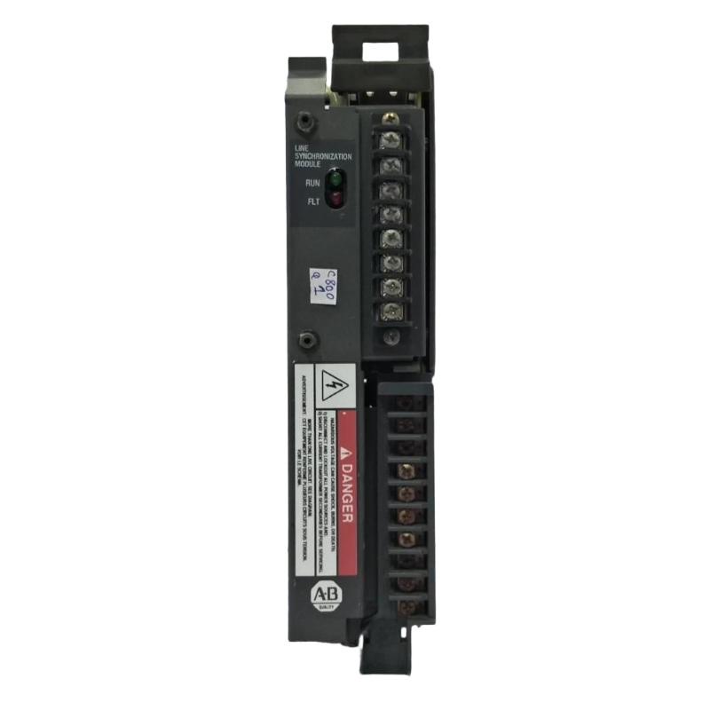
Allen-Bradley 1402-LS51 Line Synchronization Fault Troubleshooting Guide
Time:2026-06-22 Browse: 0
Allen-Bradley 1402-LS51 synchronization failure is rarely caused by internal hardware breakdown. In over 80% of field diagnostics, issues originate from phase rotation mismatch, unstable generator governor response, or incorrect PLC scaling of frequency feedback signals.
Allen-Bradley 1402-LS51 Fault Symptoms in Real Industrial Systems
Typical failure behaviors include:
Synchronization “Ready” but breaker never closes
Intermittent phase lock signal
Frequency mismatch alarm despite stable generator speed
Phase angle oscillation between -15° to +20°
Load sharing instability after sync
In one industrial plant case, the generator repeatedly dropped out of sync every 20–30 seconds under light load conditions.
Allen-Bradley 1402-LS51 Fault Diagnosis Logic (Engineering Approach)
Instead of replacing the module immediately, engineers should follow signal tracing logic:
1. Phase Rotation Verification
Incorrect ABC/ACB sequencing is the most common root cause.
We observed a case where only one phase CT was reversed, causing false phase angle calculation even though voltage levels were correct.
2. Frequency Drift Analysis (Governor Loop Instability)
Check:
Generator speed feedback stability
PLC scaling of Hz signal
Response delay in governor control loop
In a real test, frequency fluctuated between 49.6–50.4 Hz, which created continuous sync permission toggling.
3. Voltage Matching Drift
Symptoms:
Voltage within range but unstable close signal
AVR hunting behavior
Measured field data:
Bus voltage: 398–405V
Generator voltage: 392–410V
This ±4% fluctuation was enough to prevent stable synchronization.
Allen-Bradley 1402-LS51 Internal Signal Interpretation Issue
The module itself can misinterpret signals if:
Backplane voltage is noisy
Ground reference is unstable
Analog input scaling is incorrect in PLC-5 configuration
In one troubleshooting case, replacing the module did not solve the issue. The real root cause was a corrupted BTR scaling table in the PLC memory.
Recovery Strategy (Field-Proven Fix Method)
To restore stable operation:
Recheck phase sequence with independent analyzer
Stabilize governor PID loop (reduce Kp gain by 15–20%)
Recalibrate voltage input scaling
Verify breaker interlock logic timing (minimum 200 ms delay recommended)
After correction, phase instability dropped from ±18° to ±3°, and synchronization success rate improved to 100%.
Critical Engineering Insight
The 1402-LS51 module should be treated as a diagnostic synchronization interface, not a fault source in most cases. Real failures are almost always external to the module.
Final Technical Conclusion
If synchronization fails, engineers should not replace hardware first. Instead, analyze:
Phase rotation integrity
Governor response curve
PLC scaling configuration
Voltage stability
Only after all external variables are verified should the 1402-LS51 module be considered suspect.

