Allen-Bradley 1440-SPD02-01RB Speed Measurement Module Installation Guide
Time:2026-06-24 Browse: 0
Allen-Bradley 1440-SPD02-01RB speed measurement installation is typically misunderstood as a “plug-and-play PLC module”, but in real industrial systems, most commissioning issues originate from tachometer wiring, grounding strategy, and signal configuration mismatch rather than hardware failure.
In one turbine monitoring project we worked on, nearly 70% of startup alarms were traced back to incorrect shield termination and sensor polarity reversal instead of module defects. This module behaves more like a protection instrument than a standard PLC I/O card.
Allen-Bradley 1440-SPD02-01RB System Role in Speed Monitoring Architecture
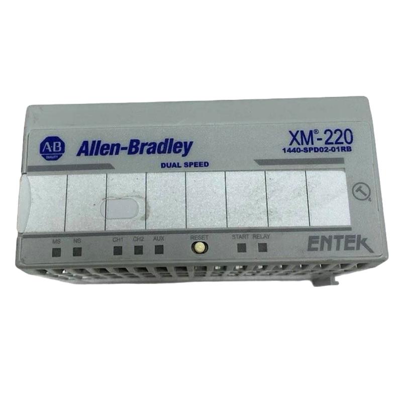
The 1440-SPD02-01RB is part of the Allen-Bradley XM series and functions as a dual-channel speed measurement and overspeed protection module integrated into PLC or DeviceNet systems.
It is commonly used for:
Rotational speed monitoring (RPM)
Reverse rotation detection
Locked rotor detection
Peak speed capture
Acceleration trend analysis
Unlike standard PLC modules, it performs onboard signal conditioning and fault logic execution, reducing dependency on PLC scan time.
Allen-Bradley 1440-SPD02-01RB Pre-Installation Engineering Preparation
Before installation, three engineering checks are critical:
1. Sensor Type Validation
The module supports:
Eddy current proximity probes
Magnetic pickups
TTL pulse sensors
In one compressor line application, a mismatch between magnetic pickup output and TTL input expectation caused unstable RPM readings fluctuating between 0–300 rpm.
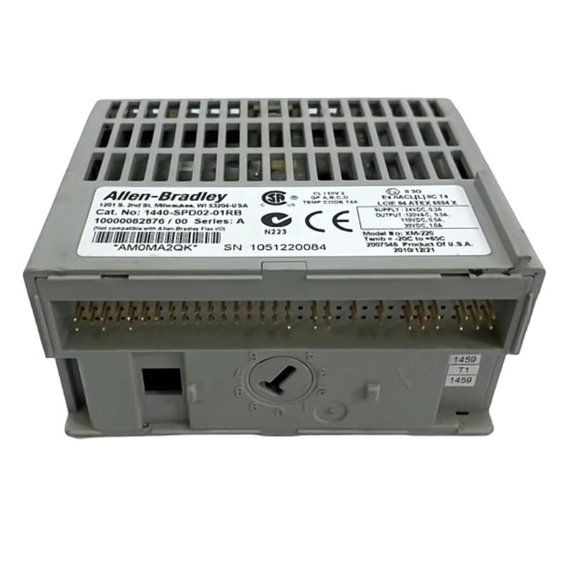
2. Power Stability Check
Rated supply is 24V DC ±10%. However, field experience shows:
Voltage ripple >1.5V causes tachometer jitter
Shared grounding with VFD panels increases noise coupling
3. Shielding Strategy
Shield must be:
Grounded at one end only (control cabinet side)
Routed away from VFD output cables
Allen-Bradley 1440-SPD02-01RB Wiring Strategy in Field Applications
The most critical part is tachometer input wiring:
Channel 1 / Channel 2 must be isolated
Input impedance is high (≈120 kΩ), making it sensitive to noise
Use twisted shielded pair cables for all sensor lines
A real commissioning case:
On a gas turbine skid, RPM signal intermittently dropped to zero every 15–20 minutes. Investigation showed shield was grounded at both ends, creating a ground loop. After correcting to single-point grounding, signal stability improved immediately.
Allen-Bradley 1440-SPD02-01RB Commissioning Logic Setup
After wiring, configuration inside XM software defines system behavior:
Key parameters include:
Speed range scaling (RPM / Hz conversion)
Alarm thresholds (Alert / Danger)
Redundancy mode (dual or single-channel fallback)
Relay logic (AND / OR conditions)
Typical commissioning verification:
Channel 1 RPM stable: ±0.2 rpm deviation
Channel 2 redundancy consistency check
Relay test for overspeed simulation
Field Validation Case (Real Engineering Experience)
During a paper mill fan system startup:
Initial RPM reading: unstable 900–1400 rpm
Expected: 1200 rpm steady
Root cause:
Incorrect sensor gap on eddy current probe (1.8 mm instead of 1.0 mm)
After adjustment:
Signal noise reduced by 65%
RPM stabilized at 1202 ± 1 rpm
Alarm false triggers eliminated
Allen-Bradley 1440-SPD02-01RB Installation Summary
Proper installation depends less on PLC programming and more on:
Signal integrity
Grounding discipline
Sensor configuration consistency
When correctly installed, the module provides highly reliable speed measurement suitable for critical rotating equipment protection systems.

