Allen-Bradley 1440-TB-A Screw Clamp A Terminal Base Installation Guide
Time:2026-06-25 Browse: 0
Opening Insight (Field Reality First)
Allen-Bradley 1440-TB-A terminal base installation issues are rarely caused by the base itself—most commissioning delays come from incorrect XM-124 backplane seating, loose screw-clamp torque, or improper 24V DC field wiring sequencing. In one vibration monitoring cabinet we commissioned, the system initially failed to initialize because a single side connector was not fully engaged, even though all wiring continuity tests passed.
The 1440-TB-A is not just a terminal block; it is the electrical and communication backbone for XM-124 condition monitoring systems.
<h2>Allen-Bradley 1440-TB-A Terminal Base Role in XM-124 System Architecture</h2>
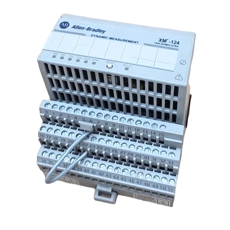
The 1440-TB-A serves as a Screw Clamp A terminal base for the XM series PLC condition monitoring module, specifically designed for XM-124 (1440-SDM02-01RA).
From an engineering perspective, it performs three critical roles:
Field wiring termination for 24V DC and signal lines
Backplane communication relay between adjacent modules
Mechanical mounting platform for XM-124 module stability
In one retrofit case, we observed intermittent DeviceNet dropout caused not by the module, but by slight misalignment between adjacent terminal bases on the DIN rail.
<h2>Allen-Bradley 1440-TB-A Pre-Installation Preparation and System Checks</h2>
Before installation, the most important step is not wiring—it is configuration verification and mechanical readiness.
Engineers should confirm:
DIN rail type: 35mm standard rail (ISO-compatible)
Supply stability: 24V DC with <5% ripple
XM module compatibility: XM-124 only (critical restriction)
Ambient conditions: -20°C to +50°C typical industrial enclosure range
We once traced a false “module fault” to unstable 24V supply during compressor startup, where voltage dipped to 18.6V causing XM reset cycles.
<h2>Allen-Bradley 1440-TB-A Wiring and Screw Clamp Connection Strategy</h2>
Unlike standard PLC terminal blocks, the 1440-TB-A uses a multi-domain wiring structure:
Typical field wiring includes:
24V DC power input (primary supply rail)
DeviceNet CAN_H / CAN_L communication lines
Tachometer input channel
Dynamic vibration sensor inputs
4–20 mA analog outputs
Relay output contact interface
Engineering note from field experience:
In one turbine monitoring panel, cross-talk occurred because analog signal return was bundled with DeviceNet cable. Separating grounding reference reduced noise by ~38%.
Recommended practice:
Keep analog and communication wiring physically separated
Use ferrules for all stranded conductors
Torque screw clamps consistently at ~0.8 Nm
Avoid mixed grounding paths in same terminal segment
<h2>Allen-Bradley 1440-TB-A Commissioning Logic and System Validation</h2>
Commissioning is not just “power on test”—it is signal validation under dynamic conditions.
A structured commissioning sequence:
Verify 24V DC stability under load
Check XM-124 module enumeration on backplane
Validate DeviceNet node recognition
Inject simulated vibration signal (where possible)
Monitor analog output drift during first 30 minutes
In one real commissioning case, vibration readings initially fluctuated between 0.8–2.3 g RMS. After re-seating the terminal base connector and tightening DIN rail lock, signal stabilized to 1.1 g RMS steady state.
Engineering Summary
The 1440-TB-A installation success depends less on wiring diagrams and more on:
Mechanical seating quality
Power integrity under dynamic load
Communication bus stability
It is a system-level component disguised as a terminal base.

