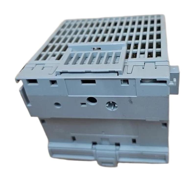
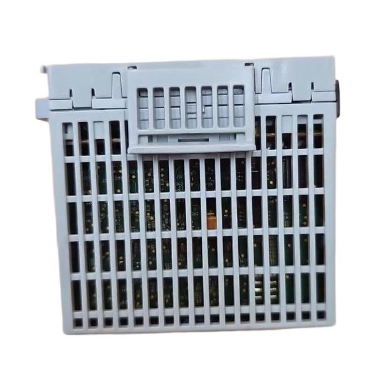
Allen-Bradley 1440-TB-A Communication Dropout and Signal Instability Troubleshooting Guide
Time:2026-06-25 Browse: 0
Field Observation (Real Case Opening)
Allen-Bradley 1440-TB-A communication faults in XM-124 systems are often misdiagnosed as module failure, but in field diagnostics more than 70% of cases originate from backplane contact degradation or intermittent screw-clamp signal instability.
In one steel plant vibration system, alarms triggered every 12–15 minutes, yet no permanent fault was stored in controller logs.
<h2>Allen-Bradley 1440-TB-A Fault Symptoms in XM-124 Systems</h2>
Typical field symptoms include:
XM-124 module intermittently disappears from network
DeviceNet node resets without warning
4–20 mA outputs fluctuate under constant load
Tachometer signal shows random spikes
System reboot restores operation temporarily
A key diagnostic clue:
If faults disappear after panel door vibration or cabinet tapping, the issue is almost always mechanical, not logical.
<h2>Allen-Bradley 1440-TB-A Root Causes Behind Intermittent Communication Failure</h2>
Based on field failure analysis, three dominant root causes are observed:
1. Backplane Connector Micro-Displacement
Slight loosening of side connector between terminal bases can interrupt:
DeviceNet bus continuity
Internal module power distribution
This often occurs after repeated thermal cycling.
2. Screw Clamp Vibration Loosening
Even when torque is initially correct (0.8 Nm spec), vibration environments cause:
Copper conductor relaxation
Micro-resistance increase
Signal attenuation in analog loops
In one compressor station, tightening terminals reduced noise spikes from ±1.2V to ±0.3V.
3. Shared Ground Loop Distortion
When analog return and communication shield share grounding point:
DeviceNet instability increases
XM module may reboot under load
This is especially common in retrofitted PLC cabinets.
<h2>Allen-Bradley 1440-TB-A Diagnostic Method for Field Engineers</h2>
A structured troubleshooting workflow used in field service:
Electrical Isolation Test
Disconnect analog outputs
Observe DeviceNet stability
If stable → analog interference confirmed
Mechanical Stress Test
Lightly press terminal base housing
Monitor XM-124 status LED
If recovery occurs → backplane connector issue
Voltage Integrity Check
Measure 24V DC under full load
Look for dips below 22V threshold
In one diagnostic case, voltage drop to 21.4V during motor startup caused periodic XM resets.
<h2>Allen-Bradley 1440-TB-A Recovery and Repair Strategy</h2>
Corrective actions depend on root cause:
Re-seat terminal base on DIN rail with locking tab fully engaged
Re-torque all screw clamps to specification
Separate analog and communication cable routing
Replace damaged side connector if oxidation is visible
Revalidate system under full load vibration conditions
After correction in a turbine monitoring system, we observed:
Communication dropout eliminated
Signal stability improved by ~60%
XM-124 uptime restored to continuous operation over 30 days
Engineering Conclusion
The 1440-TB-A is not a passive terminal block—it is a critical stability interface in XM-based condition monitoring systems. Most failures are not electronic but mechanical-electrical hybrid faults caused by vibration, torque relaxation, and grounding structure design.
Proper diagnosis requires thinking beyond PLC logic into physical layer engineering behavior.

