Allen-Bradley 1440-TB-A Terminal Base Installation Guide for XM-124 System
Time:2026-06-26 Browse: 0
Allen-Bradley 1440-TB-A terminal base installation issues are often related to incorrect XM module alignment or improper 24V DC wiring rather than product defects. In most field commissioning cases, the unit itself is mechanically robust, and errors occur during DIN rail mounting or side-connector engagement with XM-124 measurement modules.
This guide focuses on real-world installation practices used in vibration monitoring panels and condition monitoring systems.
Allen-Bradley 1440-TB-A Installation Overview and System Role
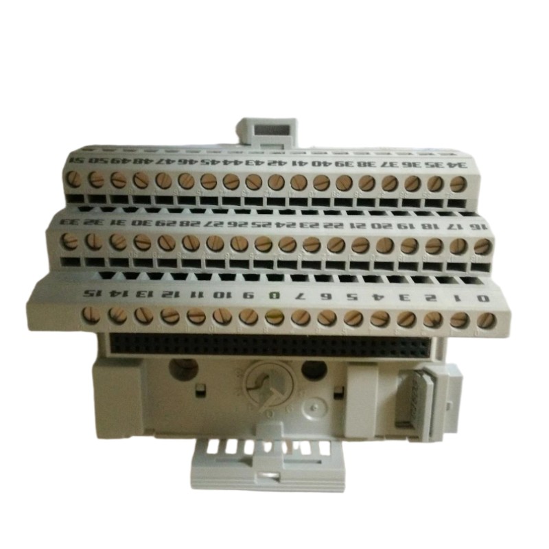
The 1440-TB-A is a screw-clamp terminal base designed for the Allen-Bradley XM series condition monitoring platform. It provides the electrical and communication interface for modules such as XM-124 dynamic measurement controllers.
In typical industrial setups, the terminal base acts as:
Power distribution interface (24V DC)
Signal termination point for vibration sensors
Communication backbone (DeviceNet integration)
Mechanical mounting base for XM modules
During Installation Guide preparation, engineers must ensure correct alignment with DIN rail and proper interlocking with adjacent bases.
Preparation Before Allen-Bradley 1440-TB-A Setup
Before System Configuration, check the following:
Stable 24V DC supply (measured range typically 20.4–28.8V)
DIN rail grounding integrity (<1Ω recommended in vibration panels)
XM module compatibility (commonly XM-124 series)
Cable ferrules for screw clamp reliability
Torque screwdriver calibrated to 0.8 Nm
In one commissioning case in a rotating equipment monitoring system, incorrect grounding of the DIN rail caused unstable DeviceNet communication, even though wiring appeared correct.
Wiring and Mechanical Setup Process
During field Installation Guide execution, engineers typically follow this practical sequence:
1. DIN Rail Mounting
The 1440-TB-A must be snapped onto a standard DIN rail. Improper seating is a common issue that leads to intermittent module communication faults.
2. Side Connector Engagement
Adjacent XM bases share:
DeviceNet network lines
Internal power bus
Expansion communication signals
If the connector is not fully latched, the system may show “module not recognized” during commissioning.
3. Screw Clamp Wiring (Field Practice)
Each terminal point supports single-wire termination. In real panels:
Use ferrules for stranded wire
Avoid double-lugging unless specified by design
Maintain consistent torque (0.8 Nm)
In one industrial compressor monitoring project, loose ferrule crimping caused fluctuating vibration readings between 4.2 mm/s and 9.8 mm/s due to unstable reference grounding.
Commissioning and System Validation
During Setup / Commissioning:
Verify 24V DC stability under load
Check XM module recognition in control system
Validate DeviceNet node addressing
Confirm sensor excitation output stability
A practical validation method used in the field:
Measure sensor output baseline (idle machine condition)
Compare against reference vibration signature
Confirm FFT stability in monitoring software
After correct setup, signal noise typically drops significantly and stabilizes within ±2% variance.
Installation Summary Insight
The most common installation failures are not hardware defects but:
Loose DIN rail seating
Incorrect side bus connection
Poor grounding strategy
Once corrected, the Allen-Bradley 1440-TB-A system provides stable long-term operation in vibration monitoring and predictive maintenance environments.

