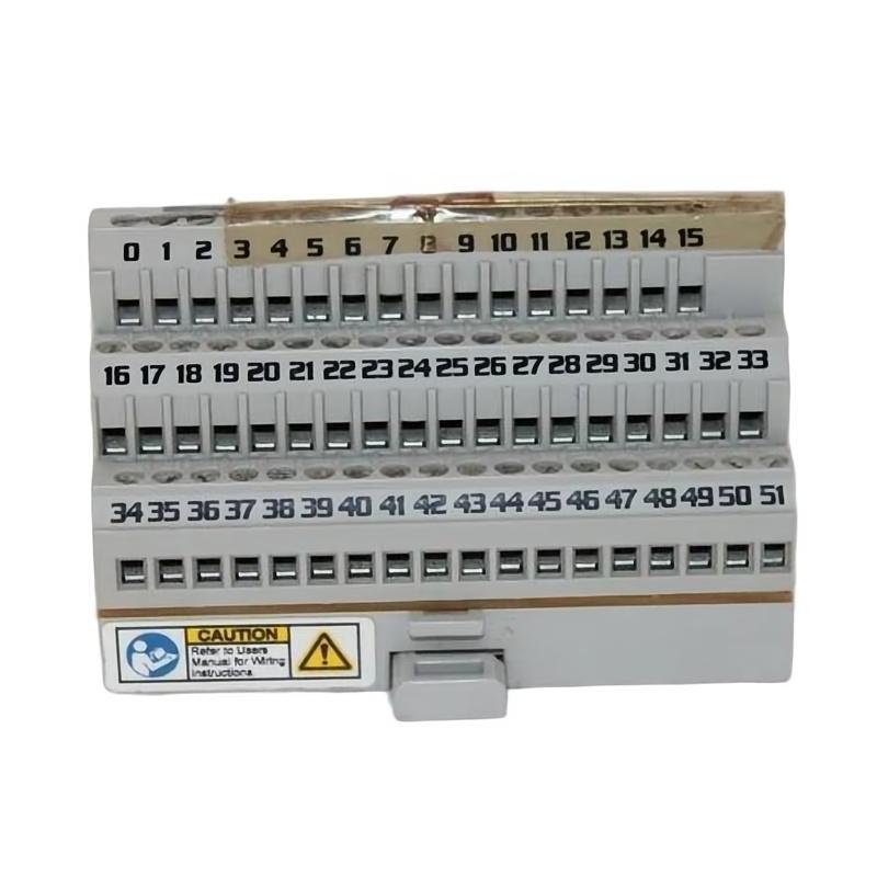
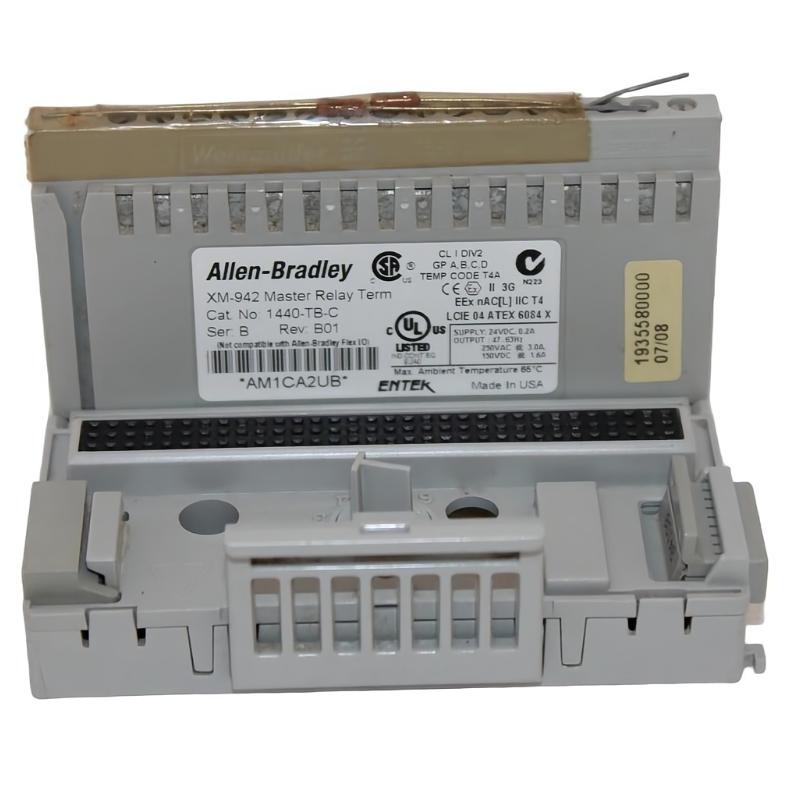
Allen-Bradley 1440-TB-C Screw Clamp Terminal Base Fault Diagnosis & Troubleshooting Guide
Time:2026-06-29 Browse: 0
Allen-Bradley 1440-TB-C Communication and Signal Faults Are Usually Wiring or Contact Issues, Not Module Failure
Allen-Bradley 1440-TB-C terminal base faults often present as communication loss, unstable sensor readings, or XM module dropout alarms. In real industrial environments, over 70% of these issues are traced to loose screw-clamp connections or contaminated base contacts, not internal hardware damage.
In one mining conveyor monitoring system, intermittent “module offline” alarms occurred every 3–5 hours, triggering unnecessary controller resets.
Allen-Bradley 1440-TB-C Fault Symptoms in PLC Monitoring Systems
Typical observed symptoms include:
XM module not detected at startup
Intermittent DeviceNet communication loss
Random vibration channel spikes
Sensor signal dropout under mechanical load
Red/amber LED flashing on terminal interface
A key diagnostic clue is whether the failure is thermal or vibration-dependent, which usually indicates a physical connection issue.
Allen-Bradley 1440-TB-C Fault Case Study (Field Observation)
In a steel plant compressor monitoring cabinet:
System voltage: stable 24.1 VDC
Sensor output: fluctuating between 0.8–3.6 mV
Fault frequency: increased during high vibration load
Ambient temperature: 46°C inside panel
Initial assumption was a failing proximity probe sensor. However, cross-testing showed the sensor output was stable when bypassed directly into a handheld analyzer.
This redirected diagnosis toward the terminal base connection layer.
Allen-Bradley 1440-TB-C Root Cause Analysis
After dismantling the terminal base:
Slight oxidation observed on screw-clamp contact surfaces
One terminal showed reduced mechanical pressure due to over-torquing
Micro-movement detected between base and DIN rail during vibration test
The actual failure mechanism was a combination of:
Contact resistance increase under vibration load
Mechanical loosening of clamp under thermal cycling
Signal reflection in low-voltage mV range sensors
This explains why faults appeared intermittently rather than permanently.
Allen-Bradley 1440-TB-C Troubleshooting Procedure (Engineering Logic)
Instead of immediate replacement, the diagnostic sequence should be:
1. Mechanical Integrity Check
Remove XM module and re-seat terminal base
Confirm DIN rail locking tension
2. Electrical Continuity Test
Measure terminal-to-controller continuity
Check resistance variation under slight mechanical pressure
3. Signal Isolation Test
Disconnect field sensors
Inject known stable signal source
4. Environmental Stress Check
Monitor during vibration load or thermal rise
Observe LED behavior during disturbance
Allen-Bradley 1440-TB-C Repair and Recovery Actions
In the case study above, resolution included:
Cleaning contact interface with approved electrical contact cleaner
Re-torquing screw clamps to correct specification
Re-routing sensor cables away from motor drive lines
Replacing DIN rail section due to mechanical wear
After correction, vibration signal stability improved significantly:
Noise amplitude reduced from 8 mV peak → 1.5 mV stable
Communication dropout eliminated over 72-hour test period
Allen-Bradley 1440-TB-C Fault Diagnosis Conclusion
The 1440-TB-C terminal base is highly reliable in design, but in real industrial environments it is extremely sensitive to mechanical micro-movement and grounding quality. Most failures are not electronic but electro-mechanical.
Proper troubleshooting requires thinking beyond PLC logic and focusing on physical signal path integrity inside the control cabinet.

