Allen-Bradley 1440-TB-C Screw Clamp Terminal Base Installation Guide
Time:2026-06-29 Browse: 0
ABB 1440-TB-C PLC Terminal Base Installation Issues Are Often Caused by Incorrect DIN-Rail Seating or Field Wiring Errors
Allen-Bradley 1440-TB-C screw clamp terminal base installation problems are rarely due to hardware defects. In most commissioning cases, issues originate from incorrect module seating on the DIN rail or mismatched field wiring between the XM system controller and the terminal base interface.
In one vibration monitoring cabinet retrofit, the system initially failed to recognize the terminal base after installation. The controller remained in “module not responding” status even though power was present.
Allen-Bradley 1440-TB-C Terminal Base System Overview and Functional Role
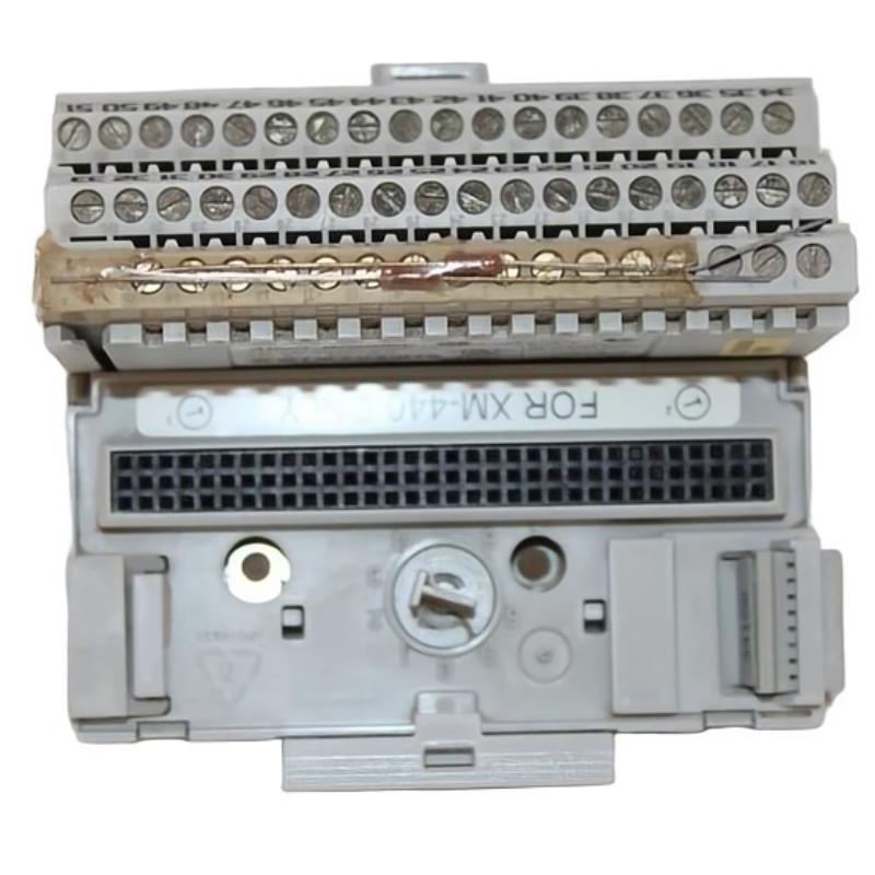
The 1440-TB-C is a DeviceNet / XM-series screw clamp C terminal base used to interface field wiring with XM monitoring modules. It provides:
Secure screw-clamp connection for industrial vibration and process signals
Mechanical docking for XM-series modules
Structured wiring distribution for sensor inputs and power rails
Stable communication path via base-to-module contacts
In practice, this component acts as the physical and electrical foundation of the PLC monitoring module system, not just a passive connector.
Allen-Bradley 1440-TB-C Installation Preparation (Field Engineering View)
Before installation, technicians typically verify:
DIN rail grounding continuity (<0.1Ω recommended in control panels)
24 VDC supply stability (acceptable fluctuation ±10%)
Proper separation between signal and power wiring
Correct XM module compatibility (e.g., XM-124 / XM-440 family systems depending on configuration)
A common field mistake is mixing sensor shield grounding with power return grounding, which introduces noise into vibration channels.
Allen-Bradley 1440-TB-C Wiring and Mechanical Setup
During installation:
Mount terminal base on DIN rail with firm latch engagement
Verify base alignment before inserting XM module
Tighten screw-clamp terminals to manufacturer torque specification
Route sensor wiring away from contactor and VFD cables
In one commissioning case, a proximity probe channel showed unstable 8–12 mV noise fluctuations. After rewiring and physically separating the sensor cable from a 3-phase motor cable tray, the noise dropped to stable sub-2 mV levels.

Allen-Bradley 1440-TB-C Commissioning and Validation
After installation:
Confirm module recognition on XM controller
Check DeviceNet communication status LEDs
Validate sensor signal stability under machine idle condition
Perform vibration baseline recording
In field practice, stable installation is confirmed only after 24-hour continuous signal monitoring without dropout or drift.
Allen-Bradley 1440-TB-C Installation Conclusion
Proper installation of the 1440-TB-C is less about mechanical mounting and more about signal integrity design and grounding discipline. Most “faults” reported at startup are resolved by correcting wiring topology rather than replacing hardware.

