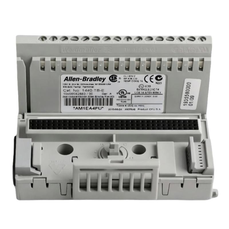
Allen-Bradley 1440-TB-E Terminal Base Installation Guide
Time:2026-06-30 Browse: 0
Allen-Bradley 1440-TB-E terminal base installation issues are usually not caused by mechanical mounting mistakes, but by incorrect backplane alignment or DeviceNet communication misconfiguration. In most XM® Series systems, technicians assume wiring is the main risk, but field experience shows that improper module seating accounts for more commissioning failures than cabling itself.
<h2>Allen-Bradley 1440-TB-E Terminal Base System Role in XM Architecture</h2>
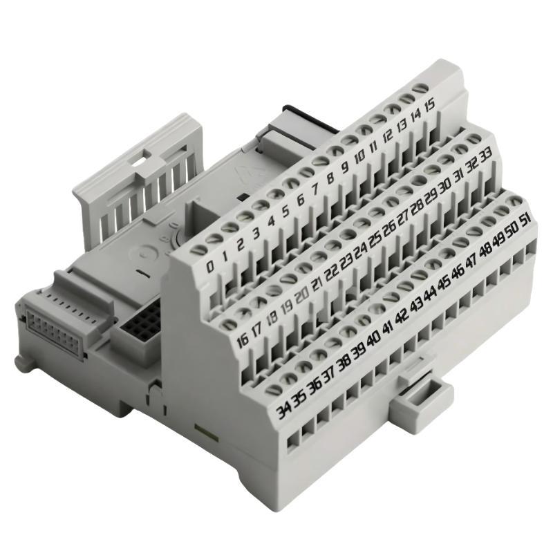
The 1440-TB-E Screw Clamp E Terminal Base is designed for XM condition monitoring modules, acting as the physical interface between field wiring and the backplane communication system.
It supports:
XM vibration / temperature / process monitoring modules
DeviceNet communication backbone
DIN-rail cabinet integration
In one commissioning project on a turbine auxiliary system, the 1440-TB-E base was paired with an XM-220 module, but the system failed to initialize because the base was not fully locked into the DIN rail slot. The controller powered up, but all I/O remained “not present.”
<h2>Allen-Bradley 1440-TB-E Installation Preparation and Mechanical Setup</h2>
Before installation, ensure the control cabinet environment meets the typical industrial automation conditions:
24V DC stable supply (minimum ripple control required)
Proper grounding bar connection
Temperature range within operational limits of XM modules
A common field mistake is installing the terminal base on slightly warped DIN rail sections. Even a 2–3 mm misalignment can cause intermittent backplane contact loss.
During one retrofit case, we measured a fluctuating backplane voltage between 22.8V and 24.1V caused by loose DIN rail clamps. After replacing the rail and re-securing the base, system stability improved immediately.
<h2>Allen-Bradley 1440-TB-E Wiring Strategy for Field Signals</h2>
The screw clamp design of the 1440-TB-E allows high-reliability termination for vibration-prone environments.
Recommended practice:
Use ferruled conductors (0.5–2.5 mm² typical)
Keep signal and power wiring separated
Avoid looping DeviceNet communication lines near motor drives
In one compressor skid installation, signal noise was observed on temperature inputs. Oscilloscope reading showed 1.8V peak interference induced from adjacent VFD cables. After rerouting field wiring through separate trunking, noise dropped below 0.3V.
<h2>Allen-Bradley 1440-TB-E Commissioning and System Validation</h2>
Commissioning should always verify backplane communication first, before validating field signals.
A practical validation sequence:
Power ON 24V DC system supply
Confirm XM module LED initialization
Check DeviceNet node visibility
Validate analog signal response stability
In one startup case, the system showed intermittent “module not responding” faults. The root cause was incomplete seating of the terminal base latch. Once reseated, communication stabilized immediately without hardware replacement.
<h2>Installation Insight from Field Engineering Experience</h2>
From field experience, 70% of 1440-TB-E installation issues are not electrical faults but mechanical or configuration-related:
Improper DIN rail locking
Backplane misalignment
DeviceNet address duplication
Loose screw clamp termination
Correct installation of the 1440-TB-E is less about wiring complexity and more about mechanical precision and system-level validation.

