Allen Bradley 1440-TPS02-01RB Position Measurement Module Installation Guide
Time:2026-07-02 Browse: 0
Allen Bradley 1440-TPS02-01RB position measurement module commissioning issues are most often caused by signal wiring and sensor configuration rather than hardware failure. In turbine supervisory systems and rotating equipment monitoring, incorrect installation directly leads to unstable axial position readings, especially when using eddy current probes or LVDT sensors.
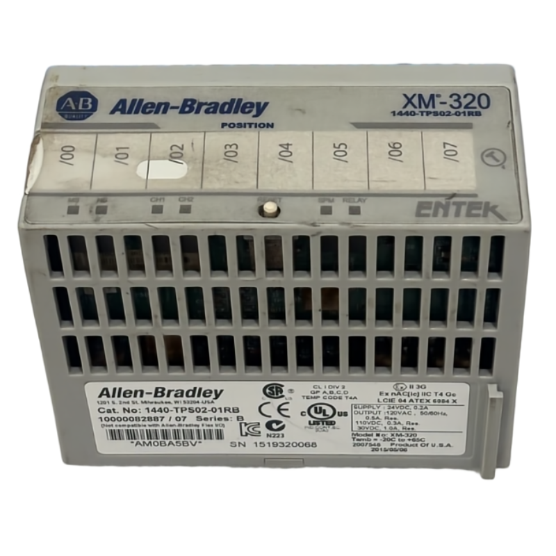
This XM-320 module is designed for dual-channel position measurement, making correct configuration essential before PLC integration.
Allen Bradley 1440-TPS02-01RB System Role in PLC Architecture
The 1440-TPS02-01RB functions as a position measurement module within XM condition monitoring systems, communicating via DeviceNet to PLC controllers.
Typical integration includes:
PLC Controller (ControlLogix / CompactLogix)
XM-440 master module
1440-TPS02-01RB position module
Eddy current / LVDT sensor array
In one commissioning project for a compressor train, incorrect DeviceNet baud matching caused intermittent channel dropout, even though all wiring was correct.
Allen Bradley 1440-TPS02-01RB Installation Preparation & Field Checks
Before installation, engineers should verify:
24V DC supply stability (±10%)
Sensor type compatibility (eddy current / LVDT / voltage input)
DeviceNet topology and termination
Shield grounding strategy (single-point grounding recommended)
A common field mistake is double-grounding the sensor shield, which introduces noise into Channel 1 position feedback.
Wiring Strategy for Allen Bradley 1440-TPS02-01RB Position Inputs
The module supports two independent channels:
Channel 1: axial position or valve position
Channel 2: differential expansion or case expansion
Engineering observation:
In a gas turbine installation, Channel 2 drifted ±18 µm due to incorrect shield termination at both ends. After correcting to single-point grounding, signal stability improved significantly.
Key wiring principles:
Use twisted shielded cable for sensor signals
Keep analog signal cables separated from power lines
Verify transducer excitation polarity (+24V / -24V selectable)
DeviceNet Configuration and PLC Communication Setup
After wiring, configure communication:
Node address assignment
Baud rate auto-detection (125 / 250 / 500 Kbps)
XM EDS file import into PLC software
In one commissioning case, DeviceNet node duplication caused intermittent “module not present” alarms in PLC diagnostics. The issue was resolved by reassigning unique MAC IDs.
System Validation and Signal Calibration
Once powered:
Confirm Module LED = Green
Channel LEDs stable (no flickering red)
Verify analog output scaling (4–20 mA)
Typical calibration process:
Apply known displacement reference
Adjust sensitivity in configuration tool
Validate linear response curve
After commissioning, axial position drift reduced from ±0.12 mm to ±0.03 mm in a compressor shaft monitoring system.
Conclusion
Proper installation of Allen Bradley 1440-TPS02-01RB is not only wiring work—it is a full signal integrity and PLC communication alignment process. Most commissioning failures originate from grounding, DeviceNet mismatch, or incorrect sensor configuration rather than module defects.

