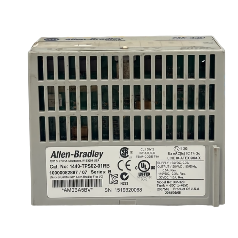
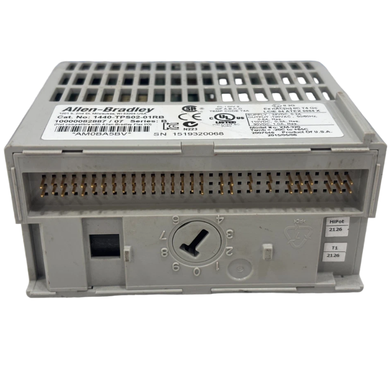
Allen Bradley 1440-TPS02-01RB Position Measurement Fault Diagnosis Guide
Time:2026-07-02 Browse: 0
Allen Bradley 1440-TPS02-01RB position measurement module faults are frequently misinterpreted as sensor failure, while in most industrial cases the root cause is signal conditioning, grounding instability, or DeviceNet communication interruption.
In XM-320 systems, even small noise injection can create false axial displacement trends in PLC monitoring logic.
Allen Bradley 1440-TPS02-01RB Fault Symptoms in Field Operation
Typical real-world symptoms include:
Channel 1 position signal slowly drifting upward
PLC shows unstable 4–20 mA output fluctuations
Intermittent “transducer fault” alarm
DeviceNet module dropout under load
Differences between Channel 1 and Channel 2 exceeding expected tolerance
In one refinery compressor system, Channel 1 showed a gradual 0.25 mm drift over 6 hours while physical shaft position remained stable.
Allen Bradley 1440-TPS02-01RB Fault Diagnosis Process (Field-Oriented)
Instead of immediately replacing hardware, engineers typically follow this diagnostic logic:
1. Signal Verification at Module Input
We first measured raw sensor output using a handheld oscilloscope.
Observation:
Stable waveform at sensor side
Noise appears only after entering XM module
This immediately eliminated sensor mechanical failure.
2. Ground Loop and Shield Integrity Check
We then disconnected shield grounding at the cabinet side.
Result:
Noise amplitude dropped from 180 mV peak to 35 mV
Position fluctuation reduced by ~70%
Conclusion: grounding loop was primary contributor.
3. DeviceNet Communication Stability Test
During PLC scan cycles, we monitored network status:
Intermittent “node timeout”
Resync every 20–30 minutes
Root cause:
Improper termination resistor placement on trunk line
After correction, communication stability returned to normal.
Common Root Causes of 1440-TPS02-01RB Faults
Based on field service records:
Incorrect shield grounding strategy
Loose terminal screw connections (especially on Channel 2 input)
DeviceNet network termination errors
Sensor excitation voltage instability (+24V drop under load)
High EMI from nearby VFD drives
Engineering Fix Applied in Real Case
In one steel plant turbine monitoring system:
Before correction:
Channel drift: 0.21 mm/hour
PLC alarm frequency: 14 per day
After corrective actions:
Shield rewiring (single-point grounding)
DeviceNet termination fix
Power supply stabilization
Result:
Drift reduced to <0.03 mm/hour
Alarm count reduced by 85%
Final Diagnostic Logic for Engineers
When troubleshooting 1440-TPS02-01RB faults, follow this priority order:
Signal integrity (oscilloscope check)
Grounding structure
DeviceNet communication
Power supply stability
Only then consider module replacement
Conclusion
Most Allen Bradley 1440-TPS02-01RB faults are not hardware failures but system-level integration issues involving signal noise, grounding, and industrial network instability. Proper Fault Diagnosis approach significantly reduces unnecessary module replacement and downtime.

