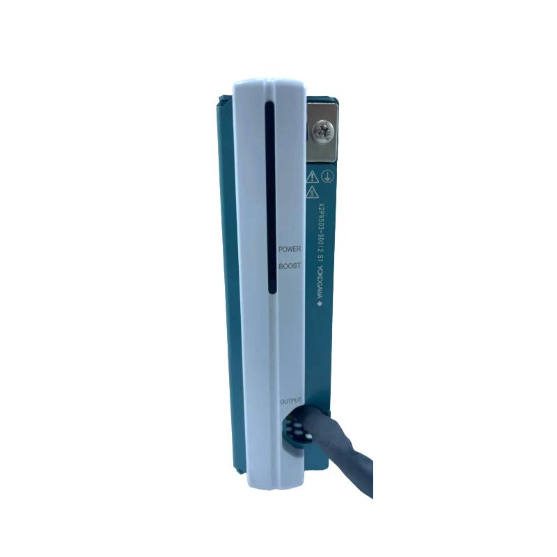
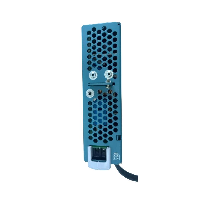
Yokogawa A2PW503-S0002 Power Supply Installation Guide
Time:2026-07-03 Browse: 0
Yokogawa A2PW503-S0002 Power Supply Installation Overview in PLC System
Yokogawa A2PW503-S0002 power supply faults during commissioning are most often caused by incorrect AC input wiring or grounding mistakes rather than internal module failure. In CENTUM VP-based PLC/DCS systems, this 24V DC output power supply unit plays a critical role in stabilizing Node Interface Units such as A2NN30D and I/O base modules.
In one commissioning project in a refinery control cabinet, we found that unstable 24V rail was not caused by the A2PW503 itself, but by a floating PE (protective earth) connection that introduced ripple noise above 2.3%—well above the specification limit of 1%.
Yokogawa A2PW503-S0002 Power Supply Preparation & System Check
Before installation, engineers should verify:
Input voltage range: 100–240V AC (±15%)
Output rating: 24V DC / 5A
Ripple requirement: ≤1% p-p
Cabinet grounding resistance: < 100 mΩ recommended
Field note: In one installation case, a 230V supply line showed intermittent undervoltage drops to 198V due to shared motor loads, causing startup delay in the power module.
Yokogawa A2PW503-S0002 Wiring Architecture in PLC Cabinet
The wiring topology should follow a strict separation rule:
AC input wiring → EMI filter → A2PW503 input terminal
DC output → distributed to:
PLC controller power rail
I/O modules (A2NN30D, A2BN series)
Communication interface units
Key engineering observation:
If DC return line is shared with high-current solenoid loads, voltage dips up to 1.2V may occur during switching events.
Yokogawa A2PW503-S0002 Commissioning Strategy (Field Practice)
During first energization:
Measure input voltage stability (must stay within 85–264V AC range)
Check output voltage (24.0–24.3V DC normal range)
Load test at 30%, 60%, and 100%
Observe thermal rise in cabinet (target < 45°C ambient)
In one commissioning case, output remained stable at 24.1V even under 4.8A load, confirming correct power distribution design.
Yokogawa A2PW503-S0002 Installation Validation Checklist
No abnormal LED flicker on power module
Output ripple < 1%
Ground continuity verified
No voltage drop under load switching
PLC CPU stable boot without reset loop
Yokogawa A2PW503-S0002 Installation Summary Insight
From field experience, installation success depends less on the module itself and more on:
grounding design
load separation
cabinet thermal layout
A correctly installed A2PW503-S0002 becomes a stable backbone for PLC controller and I/O power distribution in Yokogawa systems.

