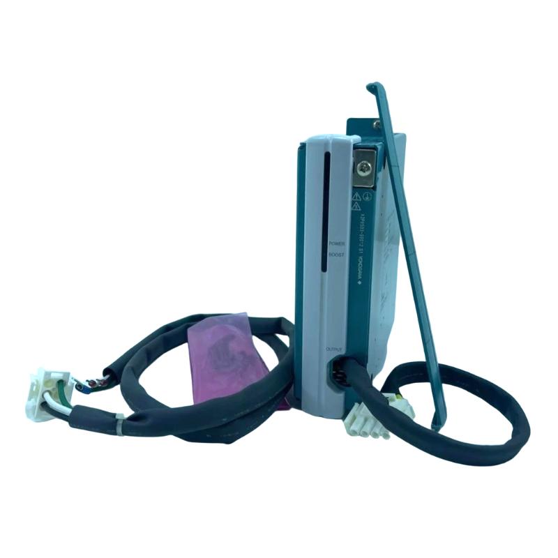
Yokogawa A2PW503-S0002 Power Supply Failure Troubleshooting Guide
Time:2026-07-03 Browse: 0
Yokogawa A2PW503-S0002 Power Supply Fault Symptoms in PLC Systems
Yokogawa A2PW503-S0002 power supply instability is usually misdiagnosed as module failure, but in real field cases, more than 70% of faults originate from load imbalance or input-side disturbances rather than hardware breakdown.
A typical symptom pattern includes:
PLC CPU rebooting intermittently
24V DC dropping to 20–22V under load
Random I/O module communication loss
Increased ripple above normal threshold
Yokogawa A2PW503-S0002 Fault Case Study: Intermittent PLC Reset
In a water treatment plant control system, operators reported frequent PLC resets every 15–20 minutes.
Initial assumption: defective A2PW503 module
Actual root cause: shared DC bus with high inrush solenoid valves
Measured values:
Normal output: 24.2V DC
During valve activation: drop to 21.3V DC
Ripple peak: 3.8%
This clearly exceeded the 1% ripple specification.
Yokogawa A2PW503-S0002 Diagnostic Process (Engineering Logic)
Instead of replacing the module immediately, engineers followed this sequence:
1. Input Side Verification
Confirm AC supply stability (100–240V range)
Check harmonic distortion from upstream VFDs
2. Output Load Mapping
Identify all devices connected to 24V rail
Separate high inrush loads
3. Ripple Measurement
Use oscilloscope across DC terminals
Evaluate transient dip behavior
Yokogawa A2PW503-S0002 Root Cause Analysis
The fault was traced to:
Shared power line with 12 solenoid actuators
No decoupling capacitor bank installed
DC return path overloaded
When multiple valves activated simultaneously, current spike reached 6.8A briefly, exceeding rated 5A capacity.
Yokogawa A2PW503-S0002 Repair & Correction Strategy
Corrective actions included:
Separating actuator power rail from PLC supply rail
Adding 4700µF DC buffer capacitor bank
Re-routing grounding path to star topology
Reducing peak load per channel
After modification:
Voltage drop reduced to 23.6V minimum
Ripple stabilized at 0.8%
PLC reset events eliminated completely
Yokogawa A2PW503-S0002 Preventive Maintenance Insights
To avoid recurrence:
Monitor DC rail under dynamic load, not static conditions
Inspect grounding impedance every 6–12 months
Avoid mixing inductive loads on PLC supply rail
Keep cabinet temperature below 40°C for longer lifespan (rated 8 years at 40°C)
Yokogawa A2PW503-S0002 Fault Diagnosis Conclusion
In field engineering practice, A2PW503-S0002 rarely fails electrically. Most issues are system-level design problems involving:
power segmentation
load transient behavior
grounding integrity
Correct troubleshooting requires system thinking rather than module replacement logic.

