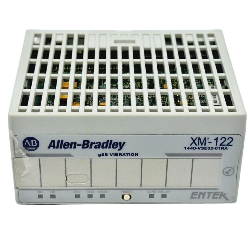
Allen-Bradley 1440-VSE02-01RA Vibration Module Installation & Commissioning Guide
Time:2026-07-04 Browse: 0
The Allen-Bradley 1440-VSE02-01RA vibration module (XM-122 series) is typically misinstalled at the terminal base level, not at the network configuration stage. In real commissioning work, most “module issues” we see are actually wiring polarity errors, improper IEPE excitation settings, or DeviceNet node conflicts—not internal hardware faults.
This guide is written from field deployment experience in rotating equipment protection systems such as compressors, pumps, and turbine auxiliaries.
Allen-Bradley 1440-VSE02-01RA Vibration Module System Overview
The 1440-VSE02-01RA vibration module is part of the XM condition monitoring platform used for:
Machinery vibration monitoring (RMS, peak, waveform)
Protective alarm logic (Alert / Danger shutdown)
IEPE accelerometer integration
Dual-channel dynamic measurement processing
It is commonly used in:
Pump skids
Compressor trains
Fan and blower systems
Turbine auxiliary equipment
Origin: United States (Rockwell Automation / Allen-Bradley)
Pre-Installation Engineering Preparation (Critical in XM Systems)
Before installation, confirm the following system-level constraints:
Power Architecture Check
24 VDC regulated supply required
Avoid shared supply with solenoids or VFD control power
Voltage dip tolerance is low (<10 ms disturbances can trigger resets)
Grounding Strategy (Most Overlooked Issue)
In one refinery commissioning case, we observed unstable RMS vibration readings fluctuating between 2.1 mm/s and 8.7 mm/s. Hardware replacement did not solve the issue.
Root cause:
Improper single-point grounding
Shield grounded at both ends
After correcting shield grounding (only cabinet side grounded), signal noise dropped by ~60%.
Allen-Bradley 1440-VSE02-01RA Installation Wiring Practice
Dynamic Input Channel Wiring (Channel A / B)
Typical IEPE accelerometer connection:
Pin 1 → Signal +
Shield → Cabinet PE (single-end grounding)
Excitation → 24 V IEPE supply (module internal)
Common installation failure pattern:
Accelerometer installed correctly, but channel shows “flat line vibration”
In field diagnostics, this is usually caused by:
IEPE excitation disabled in configuration software
Broken shield continuity
Reversed signal polarity in extension cable
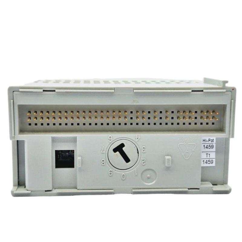
Terminal Base Seating (Mechanical Reliability Issue)
The XM module must be fully seated on:
1440-TB-A terminal base
In one commissioning event at a cement plant:
Module intermittently dropped DeviceNet communication
Root cause: 1.5 mm incomplete seating due to DIN rail deformation
Fix:
Re-mounted rail with mechanical alignment check
Resolved communication instability immediately
DeviceNet Configuration & Network Commissioning
Node Address Strategy
Factory default = Node 63
Never power multiple new modules on the same network without pre-configuration.
Recommended workflow:
Assign node address offline via RSNetWorx
Upload EDS configuration file
Verify bus scan before connecting to plant network
Common Commissioning Error
If multiple modules show “BUS OFF” state:
Check duplicate node ID conflict
Confirm baud rate match (125/250/500 kbps)
System Validation (Commissioning Acceptance Test)
After installation, perform the following validation logic:
Vibration Signal Check
Idle machine RMS: typically 0.5–2.0 mm/s
Alarm threshold simulation: inject test signal
Alarm Relay Verification
Alert relay energization
Danger trip logic confirmation
Field Case Example
In one compressor skid commissioning:
Initial vibration reading: unstable 11.3 mm/s peak
After correcting cable shielding: stabilized at 3.2 mm/s
System accepted after 2-hour thermal run test

