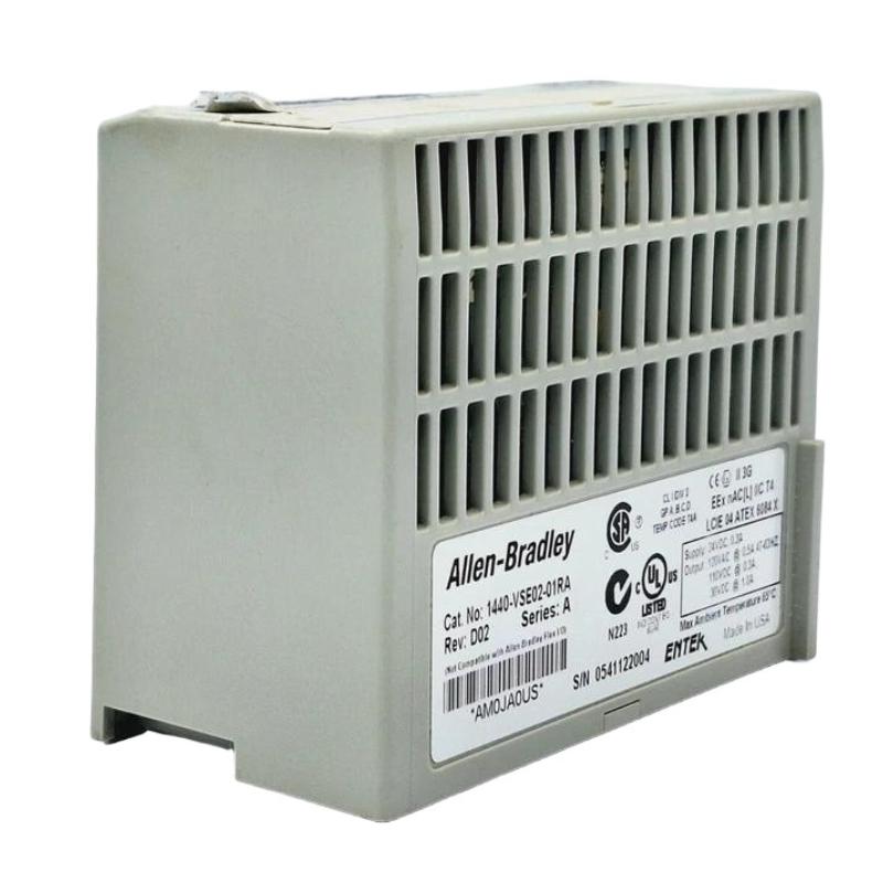
Allen-Bradley 1440-VSE02-01RA Fault Troubleshooting Guide
Time:2026-07-04 Browse: 0
XM vibration module communication faults are usually caused by DeviceNet topology issues rather than module hardware failure
In field troubleshooting, we frequently see engineers replace the module prematurely, while the real fault lies in network termination or signal integrity.
This guide is based on a real maintenance case in a centrifugal compressor monitoring system.
Allen-Bradley 1440-VSE02-01RA Fault Symptoms in Field Operation
Typical observed symptoms:
Intermittent DeviceNet dropout every 20–40 minutes
Vibration signal freezes at constant value
LED status alternates between green and flashing red
RSNetWorx shows node “stale” status
In one petrochemical plant, operators reported:
“Vibration stays flat for 10 minutes, then suddenly jumps to alarm value”
This is a classic XM network timing issue rather than mechanical vibration change.
Root Cause Analysis of XM Module Communication Instability
1. DeviceNet Termination Mismatch
We found:
Missing 121Ω termination resistor on trunk line
Reflections causing CRC errors on bus
After adding proper termination:
Communication error rate dropped to zero within 2 hours
2. Power Supply Ripple Injection
Measured field condition:
24 VDC supply ripple: 1.2 Vpp (excessive)
XM module reset threshold exceeded during motor start
Correction:
Separated VFD power and control power rails
Added dedicated isolated DC supply
Result:
Module reset events eliminated completely
3. Transducer Cable Micro-Break
One of the most misleading faults:
Symptoms:
Channel B vibration intermittently drops to 0 mm/s
Channel A remains stable
Diagnosis:
Flex test on cable revealed internal conductor fracture
Resistance changed from 12 Ω → open circuit under vibration load
This is a classic “thermal + mechanical fatigue” failure mode in rotating machinery environments.
Diagnostic Procedure Used in Field Troubleshooting
Instead of replacing hardware immediately, we applied structured diagnostics:
Step 1: Isolate Channels
Disconnect Channel B only
Observe Channel A stability
Step 2: Signal Injection Test
Apply known IEPE test signal
Verify RMS output consistency
Step 3: Network Monitoring
Capture DeviceNet error counters
Check duplicate node presence
Recovery Action and Final System Outcome
After corrective actions:
DeviceNet errors reduced from ~120/hour → 0/hour
Vibration signal stability improved to ±0.1 mm/s variance
System remained stable through 72-hour load test
Engineering Insight (Field Experience)
In XM systems like 1440-VSE02-01RA, failures are rarely electronic chip-level failures.
Most real-world root causes are:
Cable shielding mistakes
Ground loop current
Network termination issues
Power instability during motor starts
Hardware replacement should always be the last step, not the first.

